
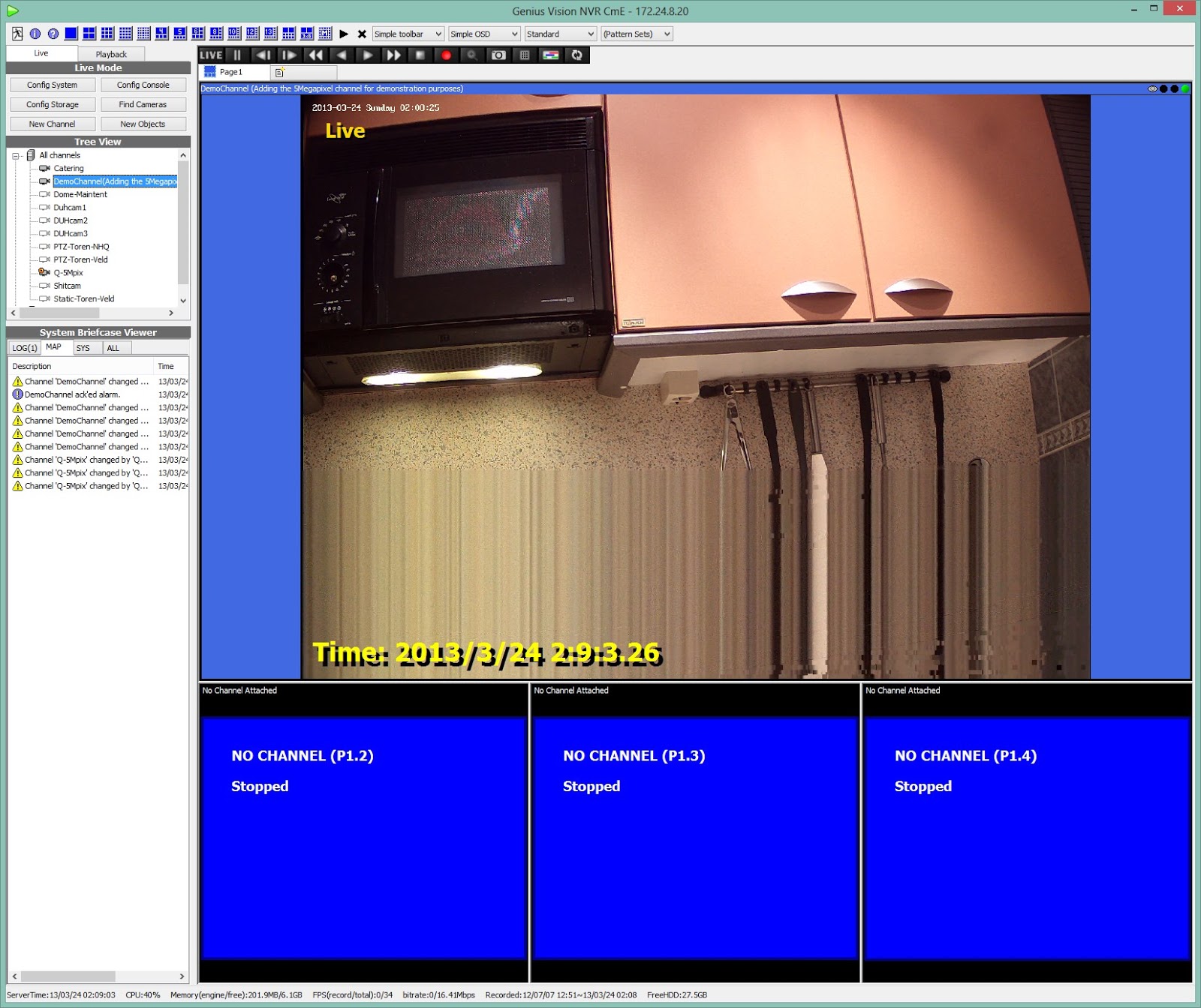
Ever since I started with the IP camera’s described in my previous posts I’ve been plagued by a problem that the RTSP streams would sometimes show corruption in the lower/bottom part of the picture as shown below:
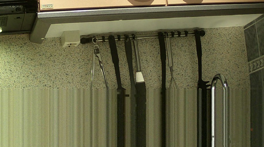
I attributed this towards either buggy firmware or other problems, but with some excellent support of Genius Vision and some research of my own I believe I have found the root causes for most of these problems. This blog post will explain which problems you might be having and also serve as a guide on how to configure and fix the problem in Genius Vision.
There seem to be two main causes I have found that is causing this problem.
Broken FFMPEG builds:
First there have been builds of FFMPEG which would show this corruption because of a bug that slipped into it’s UDP-RTSP routine. A lot of software uses these routines internally so if you are seeing the same phenomenon in the NVR software you are using, and they have not kept up their version of FFMPEG for a while, they might need to update.
The most interesting links I have been able to find about this are the following:
The problem described on the FFMPEG forum: https://ffmpeg.org/trac/ffmpeg/ticket/285
A forum post for a NVR using FFMPEG internally and showing problems: http://vitamindvideo.com/forums/viewtopic.php?f=3&t=645
A temporary fix is trying to get your stream over TCP and not UDP, but best is to get an updated version of FFMPEG in your software.
update– Since writing this I have come to the conclusion that using FFMPEG will always produce corrupted output with my 5Mpix IP camera. In my observation VLC does not have these problems because they are using the LIVE555 RTSP libraries. The RTSP implementation in FFMPEG has some serious issues handling higher MegaPixel IP cameras. For more information see the following blog post: new method using VLC. The date this article was written is 2013-03-25 and is true for all current builds of FFMPEG.
Not enough packet buffers (Genius Vision guide):
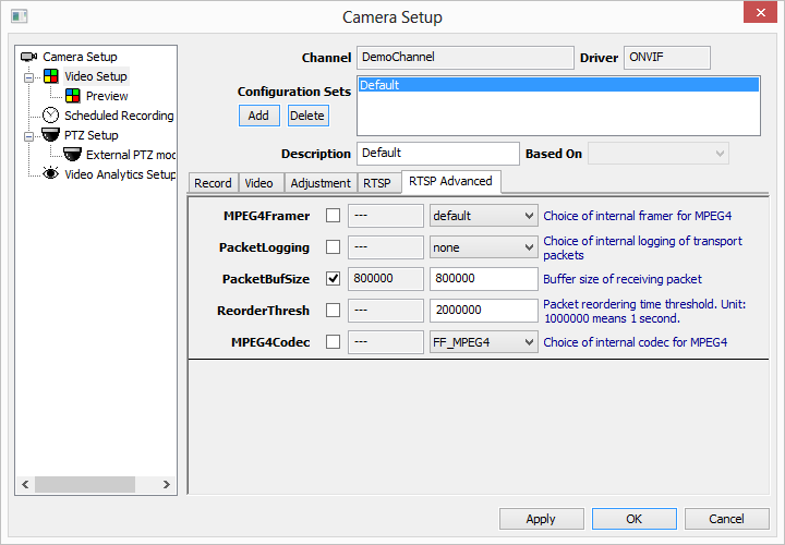
With Genius Vision the problem turned out to not be a bug but an effect of using a MegaPixel IP camera. The software has a default value for the packet buffers and this is too low for MegaPixel cameras and can cause corruption if not adjusted manually. The reason they have the setting as they have it is because they want the software to work reliably with lots of cameras connected and don’t want to waste memory when it’s not needed.
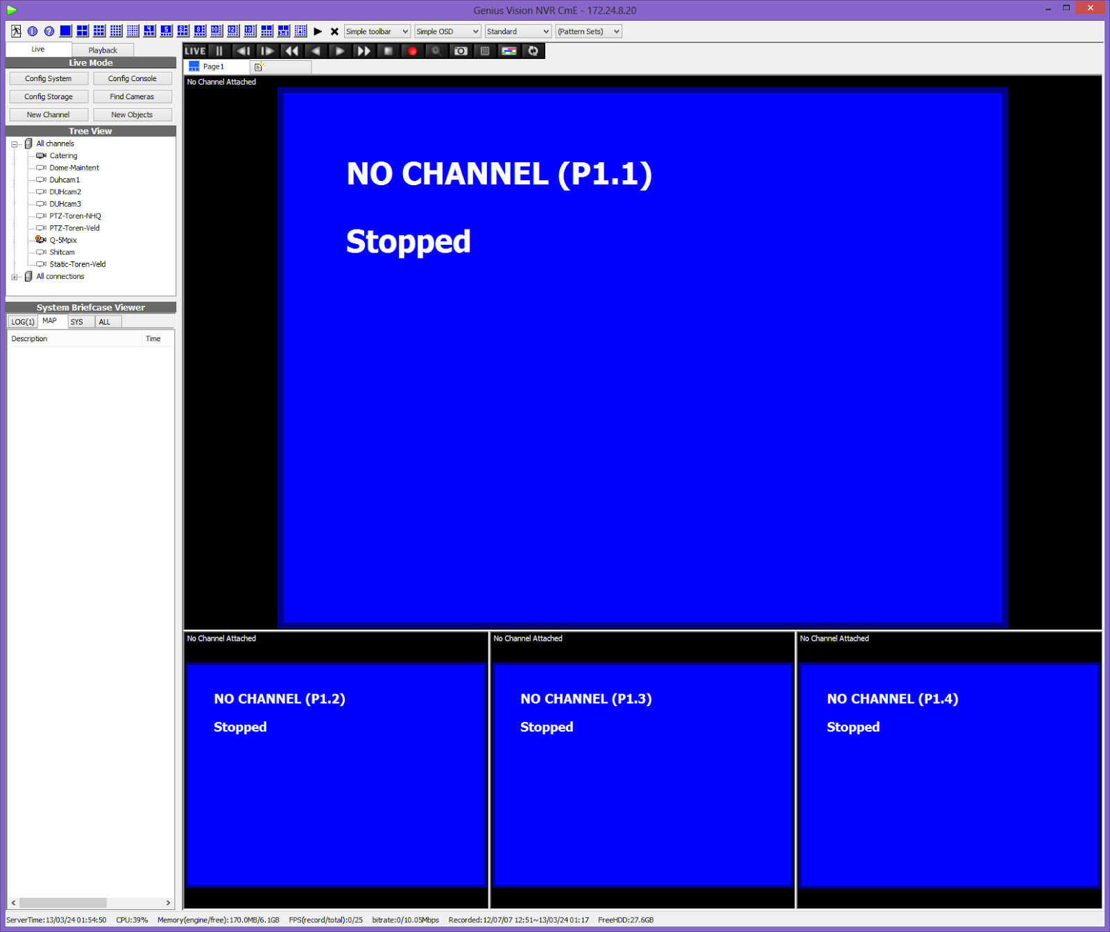
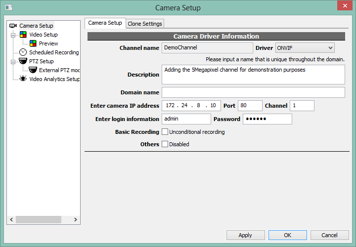
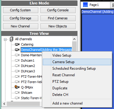
Below I will show in pictures how to add the 5Mpix camera in Genius Vision and how to set the packet buffer to remove the corruption. Although this guide is specific to my camera and Genius Vision the same should apply to any ONVIF or RSTP camera and whatever software you might be using.
I’ll be using the ONVIF method which is now available with the new firmware for the camera as described in my previous blog post.
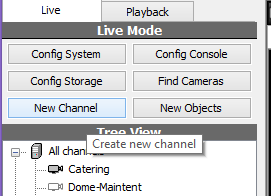
Genius Vision adding a camera:
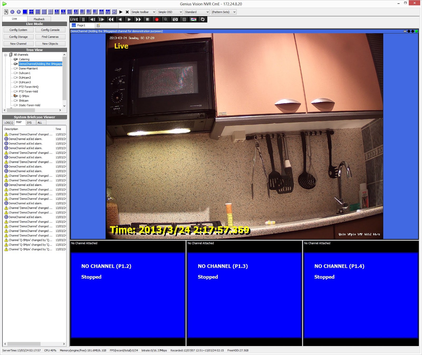
Fixing the problem:
Hi, I have installed Genius Vision but I am having a problem with remote viewing. I have Genius Vision apps on android and ipad but neither work when trying to connect remotely. Do you have any ideas on how to fix this?
Regards
Another Genius Vision application question. I have successfully and reliably used GV with 7 cameras of all sort, motion detection capability and the E-mail alerting systems with great success. I would like to connect modbus devices (Digital input and Digital Output device to Genius vision RS-485 or serial/com DIO service. I can see Genius vision generating MODBUS $016 polling call using WIRESHARK. But I have not been able to get communication established MODBUS deceives. Do you have any experience or using Genius Vision in for this control function? Joe
What kind of problems are you seeing? I have tested both Android and IOS devices and both worked fine?
Sorry to say I have no clue. I've never used any digital in/ouputs Genius Vision. Hope you can get it to work. You can always pass an e-mail to the company/creators. I've had great e-mail contact and feedback from them! 🙂
I did succeeded in connecting and controlling a DIO device. I can send and receive data packets using a 16 channel DIO TCP/IP modbus based device. Genius Vision NVR Community Edition will send polling command $016 to the device. The commands are ASCII encode hexadecimal data packet. The charter $ is a delimiter. 01 is the modbus device ID and 6 is a command function to get all DIO channels states. A modbus device designed to read that specific message protocol format will return a 16 channel data packet. Example !FFFF. This result is for 16 channels with the states set to 1. The ! delimiter indicates the data packet is good.
Once GV starts receiving good data packets the DIO GUI will be activated allowing the users to manually control the DO on/off states. Genius Vision will generate DO commands in the format @IDaabbxxxx where the character @ delimiter indictes the command to set the DO states. 01 is the DIO device ID, aa=00, bb=00 indicates all DO states are to be changed, XXXX is the DO hexadecimal formatted bytes for 16 channels. Example @010000FFFF will set all DO states to one or high. Genius Vision did provide a non-authoritative document that show how to interface a DIO device. It was not very useful to me at the time. You can get the document at https://geniusvision.net/community.html use the Search tool and the word ‘modbus’. Eventually I built some python code and forensic test scripts to communicate with GV. I found that the CD-8088 device is a 8 channel DI and 8 DO device. CD-8116 is a 16 channel DI device. CD-8216 is 16 channel DO device.
I did manage to build a python script to communicate with GV formatted DIO data packets and a very basic capability to reformat the data packet and send it to ADAM6052 16-ch Digital I/O modbus module.