The whole reason for building my own LED dimmer was because I’m currently building a new house and was unsatisfied with commercially available dimmers. They either didn’t have the features I desired or where way too expensive and often, both!
This post will describe which parts of the house will be powered using my LED dimmer solution.
Over time this plan has seen many iterations. Below is a balance of wishes and costs formed to something I’m willing/able to pay for and giving us a well lit and most importantly a controlled lighting system in our house the way we desire.
The lighting system will be built two fold. First there will be normal ceiling lights which are controlled with normal wall switches. I want something which isn’t dependent on my Domotica system which in turn relies on WiFi. If for whatever reason it would stop functioning, not being able to turn on a light would be quite a problem. So each room is getting a normal light.
Next to that I have decided where I want to have either LED downlights (in the ceiling) and/or LED strips. There will be more places lit by the system then shown here, but these are the points I need to electrician to run cables to.
Downstairs
Downstairs will be a mix of LED downlights and LED strips.
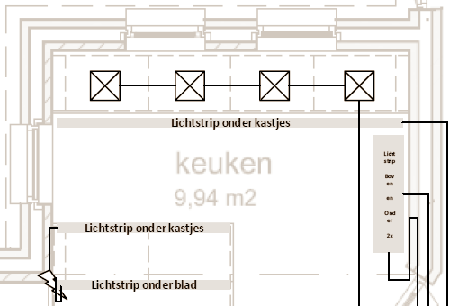
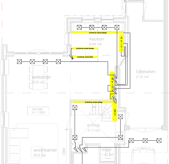
Here is the picture I made to convey my wishes to my electrician:
Click on the picture to see a larger version
Here you can see the spots in the ceiling where I wish to have a LED downlight and the places where I’m planning to use LED strip. All have wires drawn attached to them to show where I’m going to place my WiFi LED PWM dimmer module an feed in the power.
Downstairs consists of 2 locations for this. One on top of a high cabinet in the kitchen. This cabinet is 220cm high so anything on top of it shouldn’t be visible for a normal position. The ceiling is 260cm high so that leaves 40cm to work with, that should be more then plenty.
As you can see from the drawing 5 modules in the kitchen and 3 in the wiring closet. The amount isn’t final yet, but with my current 2 channel version the minimum required. When designing the plan it’s important to keep in mind what voltage you are going to use for the connected lights and what the expected voltage drop for the used cable length is going to be.
Because it’s low voltage DC cabling, voltage drop will occur over longer lengths and thus if you are connecting 2 sets of lights using one ESP dimmer you need to make sure that the cable length connected behind it is about the same. That way you can compensate using your power supply to get the voltage to the right level where the lights are. This is also the reason why I didn’t place the power supplies and Dimmer modules in the wiring closet for every light I have. The amount of wasted energy would just be too much.
Some tips through which can minimize the effect.
- Use thicker copper wire to go to the place the lights are located but in between them you can use a thinner wire (if the distance isn’t that big). Using my “system” all the lights connected to one output are wired in parallel
- Use higher voltage DC lights/strips where possible
- Use a trimmable power supply so you can compensate for the voltage loss at the “end” of the cable
The lights and strip used will be described in another blog post.
Upstairs
Let’s start with the drawing:
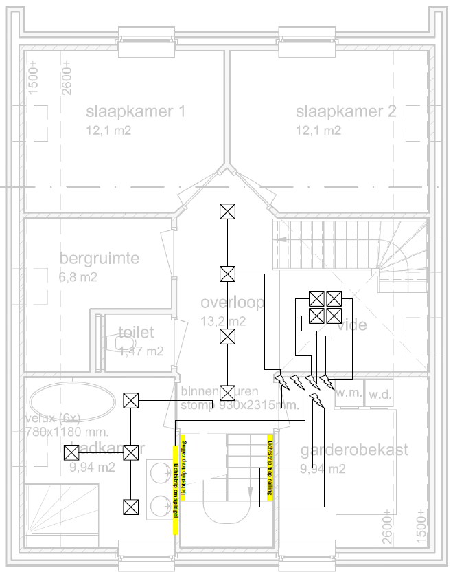
Click for a larger version
Again, several places with downlights and some light strips. The downlights will be placed in the hallway and in the bathroom to provide ampel light or softly dimmed light when desired. The one’s drawn in the vide are special, they are some chandelier type lights I bought a while back which I will fix myself using LED strip.
Again I used one spot where I will concentrate all the dimmer modules and power supplies. In this case I will need a minimum of 5 dimmer modules.
Attic
The last place is the attic. Here I’ve kept the plan quite simple. There are probably going to be more controlled lights, but since there is no real way to hide all the wires through the wall (or rather the ceiling plates) the electrician doesn’t need to do anything with it.
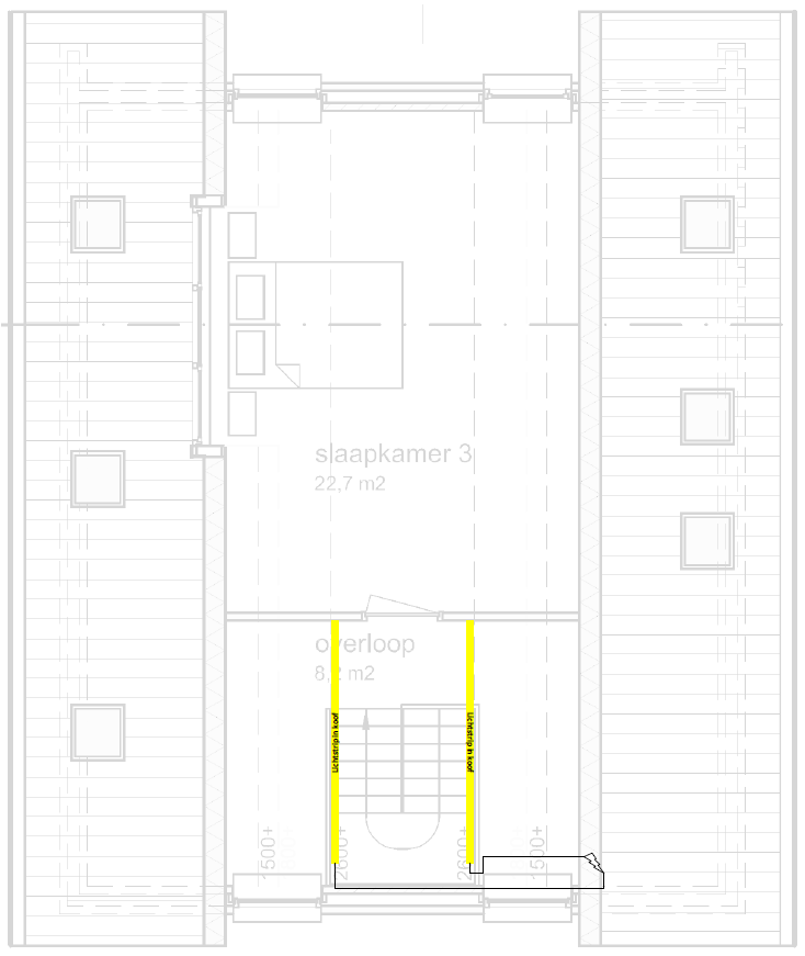
Click to see a larger version
I have planned to use two LED strips and no other lights have been planned for the electrician. Since it’s going to be a roof with exposed wooden beams I will most likely use the beams to run cables and attach some lights.
Electrician plans
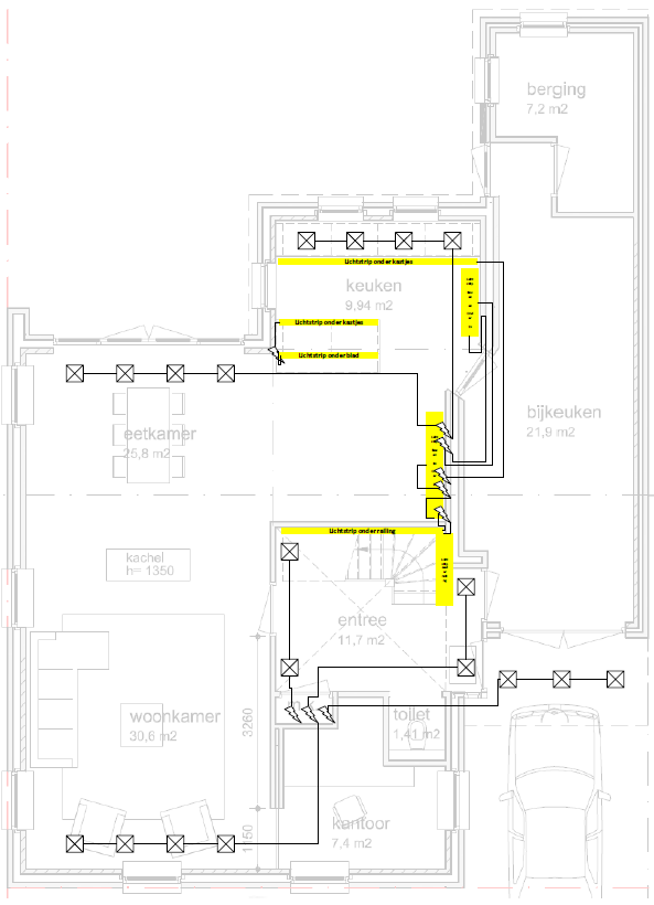
All these plans have been translated into official drawings as shown below.
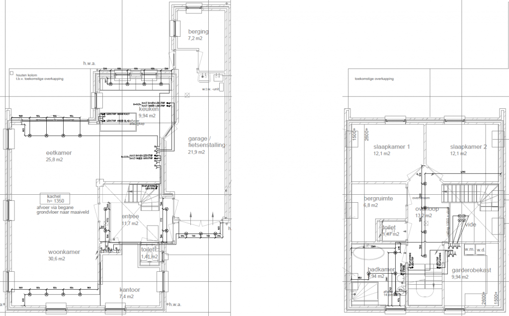
Click for a larger version (one image)
So that’s the plan. I can’t tell you if it’s going to work yet because the house hasn’t been built. But everything I’ve been designing and been building the last year tells me it should work, so I’m moving ahead with it! Hopefully we’ll be able to enjoy the lights and dimmers for a very long time!

Yo Quin, ONOK here, checkout this video: https://www.youtube.com/watch?v=OramJZmoekA&list=FLZKQ41Y9H_lbIAERAUcd9Aw&index=2
I build these and used quinled as inspiration (I used arduino nano + ethernet instead of the ESP, but the idea is the same). Good luck with the new house 🙂
Cool video! Thnx 🙂