
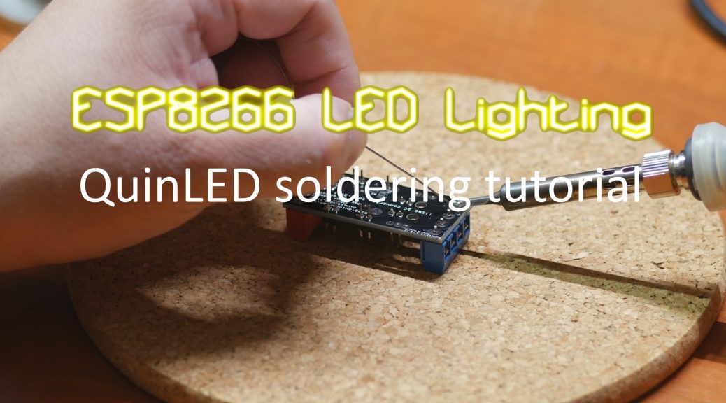
After getting all the required components together it’s time to solder them onto the QuinLED board. I made a 30 minute video going through all the steps of soldering everything together trying to show that it’s actually quite easy to do so yourself!
This post also highlights on all the tools I use while working with QuinLED. I describe most of them and explain a little bit what I use them for.
This post is part of a series
The index for this series can be found here.
Soldering video tutorial
Although I’m no wizard at soldering (I only started doing so during this project) I tried my best at making a soldering video. It took several attempts to get a half-way decent video, so I hope it’s going to help some of you and also show that it’s really quite easy to get it all to go together.
If you have any questions about getting the board soldered together, leave a comment here or on YouTube and I will try and get back to you!
Order of soldering the board
To make the soldering a bit easier, the order of soldering I use to stick it all together is as follows:
- We start off with the pin headers for the DC-DC converter, I solder these with the long leg pointed down and with the plastic spacer on the top of the board
- Next are the 2×2 pins for the jumpers and the 5×1 pin headers, these both go in with the long side and plastic spacer on top
- Then it’s best to solder the 4×2 header socket (to easily be able to disconnect or change the ESP-01)
- After that, slide the DC-DC voltage converter on the pins you soldered earlier. This can be quite a tedious process and might need you to bend some pins a little bit to get it on there. Once you get it on in the correct orientation (the little adjust screw goes closest to the ESP socket!) you can need to solder it on the top side and bottom side
- Once that’s done, solder on the 2×1 input and 4×1 output screw terminals. Be sure to use plenty of solder so that they have a good connection to the board to transport all the current
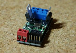
- And then we can put on the final part, the MOSFETs! Orient them so that the metal parts are both facing inward and the black side with the text is facing outward. Push them in from the top of the board to the bottom and push them as far down as they go. I mostly space them so that they are both pointing outward a bit giving better access to the jumpers in between them (Although you really only need to put the jumpers on once to flash the board)
And that’s it, your board is all together and ready for setting the voltage converter and flashing! That’s something for the next post though.
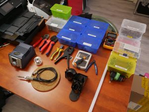
What tools are useful
In the previous part I talked about which required and optional components are needed but I didn’t talk about the tools you might need.
I suspect most of you will already have some if not all of these tools, but if you don’t I’ll try and highlight it below and also include some links where you can get it cheaply!
1. Soldering station
The most important tool you need is a soldering iron or rather soldering station. I recommend getting a fairly decent soldering station instead of an soldering iron, soldering stations are able to keep the tip at a much better constant temperature and it’s less heavy to hold in your hand, making the whole process just so much easier.
I’ll try and list several variations of which I think are decent and good to get your started:
- Cheap, I just need to get it done: Cheapest soldering station I could find
- Moderately priced: A simple but decent soldering station
- This seems great for the price: Older model high powered air + Soldering iron!
- Holy balls, give me the best: A high-power soldering station including a hot air gun and a soldering iron!
![HTB1VP4TMpXXXXc2XpXXq6xXFXXXK[1]](https://blog.quindorian.org/wp-content/uploads/2016/08/HTB1VP4TMpXXXXc2XpXXq6xXFXXXK1-300x300.jpg)
2. Soldering accessories
Next to the soldering station itself, you might need some accessories such as tin or a third hand to help you out!
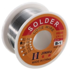
Soldering tin
You need tin to get everything to “stick”/weld together. Tin comes in lots of different variaties but most important is with or without flux/resin and the thickness of it.
- Soldering tin: 0.5mm with flux core or 0.5mm with flux core
or if you would rather solder with wire not having flux/resin inside of it you could get the following:
- Soldering tin: 0.3mm without flux core & Flux pen: No-clean flux pen
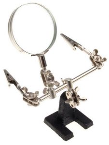
More hands!
Sometimes, you just don’t have enough hands to hold all the different pieces! That’s where a third hand comes in. The cheaper one’s only hold your board, and the more expensive one’s have a magnifying glass and LED light to help you out!
- Third-hand soldering help: 2 clips with magnifying glass or 2 clips, magnifying glass and LED light
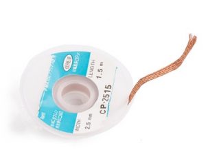
When it all goes wrong
Especially when you are starting out with soldering, things will go wrong. You will solder your components the wrong way around or even on the wrong side of the board.
With de-soldering wire and/or a de-soldering pump you can get the component loose again and correct your mistake!
- Desoldering: Desoldering wire
- Desoldering: Desoldering pump
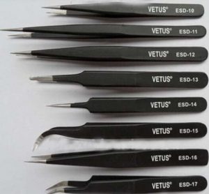
All these components are way too small!
Sometimes when you need to pick up some components or hold some opponents at a certain place (especially with SMD soldering) some tweezers can be a life saver!
Tweezers: A set of 6 different tweezers
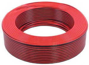
3. Electrical wire
By default, all the components have wire connected to it, but most often these are too short or don’t work for the application you are trying to achieve. For instance, the LED bars mostly only have about 10cm of wire connected.
For this I recommend getting a few spools of wire to be able to house the power supply, QuinLED board and LED lights where you need them!
Be careful when selecting the wiring gauge that you take the diameter or AWG that your application needs. More current needs thicker wire and longer distances also require thicker wire.
Take a look at the following chart to get an idea:
![DC_wire_selection_chartlg[1]](https://blog.quindorian.org/wp-content/uploads/2016/08/DC_wire_selection_chartlg1-300x179.jpg)
Better quality wire: Silicone AWG selectable wire
Nice looking wire: Cool blue sleeved wire
4. Electrical wire accessories
Most wire comes as stranded wire. While this type of wire works just fine and is easy to work with, making secure connections in screw terminals or soldering it can be a real hassle.
To overcome this problem, I use wire ferrules and crimping tools so make secure and easy dis-connectable connections!
This comes in two different variants which I both often use:
Wire end ferrules
These wire ferrules crimp on the end of a stranded wire and give one solid grippable “plug” which you can easily lock down without worrying that some strands might miss the terminal.
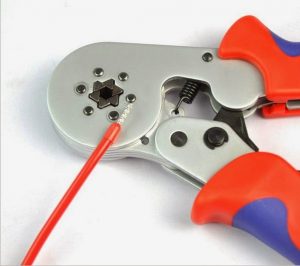
First off you need a crimping tool. These might be a bit of an investment but since I have one I don’t understand how I ever lived without it. 😉
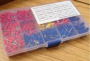
Then you need ferrules to crimp on your wires. These comes in several sizes and need to match the wire you are using, I mostly recommend getting a “ferrule kit” which as an assortment with the most commonly used sizes.
Ferrule Crimping tool: Hexagon ferrule crimping tool
Assorted Ferrule box: Box Aliexpress link
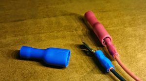
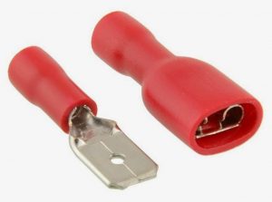
Crimped wire connectors
The second set of crimping tool and plugs I recommend getting is crimped connector plugs. These are use the make a secure and insulated connection which can also be easily disconnected!
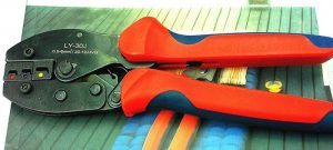
To be able to put these plugs on your cables you are going to need a different crimping tool and a set of plugs. Again, a bit of an investment but it will make your life SO much easier!
Crimping tool: Suited for the Red, Blue and Yellow plugs
Red plugs: Suited for 0.5mm2 to 1.5mm2 wire
Blue plugs: Suited for up to 1.5mm to 2.5mm wire
Yellow plugs: Suited for 4.0mm to 6.0mm wire
Since I liked to differentiate plus and minus with red and blue I use the above wire ferrules inside of the plugs to make it all fit together!
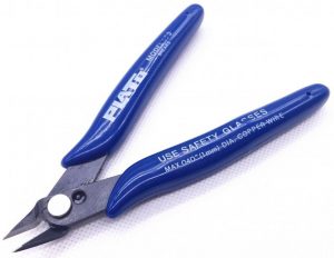
Wire snips!
You see me using these in the tutorial video. You need some good snips with which you can cut off excess headers or wire. I one with a bent beak so you can get close to the PCB and snip everything off.
Wire snips: Bent beak for cutting close to a PCB
Wire snips: More heavy duty for cutting larger size AWG wire
A great collection
If you don’t have any of the items listed above yet, hopefully this can be a good starting guide to what is useful during tinkering and “making”.
Once you have all the tools in this post and the components of the last post, you’ll have quite the collection for doing lots of projects for which you will already have a lot of tools!
All the links are for Aliexpress. I enjoy shopping there myself, I’ve never been burned by any seller there and their prices can’t be beat. Often the item price for something is cheaper then just the shipping costs here in the Netherlands.
The next article will be about setting the voltage converter to the right voltage and hooking the board up to your computer and flashing the NodeMCU firmware.
As always, any question or comments are always welcome, here or on YouTube!
Quite interesting tutorial. Actually, your soldering is pretty decent.
Quite informative. I’m pretty impressed with the ferrule kit that u have mentioned here