
The next step in the series of building your own ESP8266 is to set the voltage and flash the ESP-01 with the NodeMCU firmware!
This post is part of a series
The index for this series can be found here.
Video!
As sometimes a picture can say a thousand words, a moving picture should say a million! Here is the video that will show what next steps you need to take.
Steps in the video
Setting the DC-DC video converter
If you can’t watch the video for all the steps, here are they again in text form. However, I still strongly suggest you watch the video when you can!
The first step is setting the DC-DC voltage converter you soldered onto the board to the correct voltage (between 3.3v and 3.6v). I mostly set it to around 3.45v to give it a bit of headroom. Make sure the ESP-01 is NOT connected before you do this. If you try it before adjusting the voltage converter, the ESP-01 will go up in smoke!
The screw on the DC-DC voltage converter can be a bit of a pain to work with though so try several screwdrivers to find the one that works best for you.
Setup for flashing
After you get the right voltage dialed in we need to flash the firmware. To do that, place the two jumpers on the pins between the MOSFETs. This puts the QuinLED board (and the ESP8266 on it) into flash mode when it boots.
Then use the Dupont cables (female – female) to connect TX, RX and GND. GND is a direct connection but TX and RX need to be crossed. So connect TX -> RX and RX -> TX.
![430[1]](https://blog.quindorian.org/wp-content/uploads/2016/09/4301.gif)
Flash NodeMCU
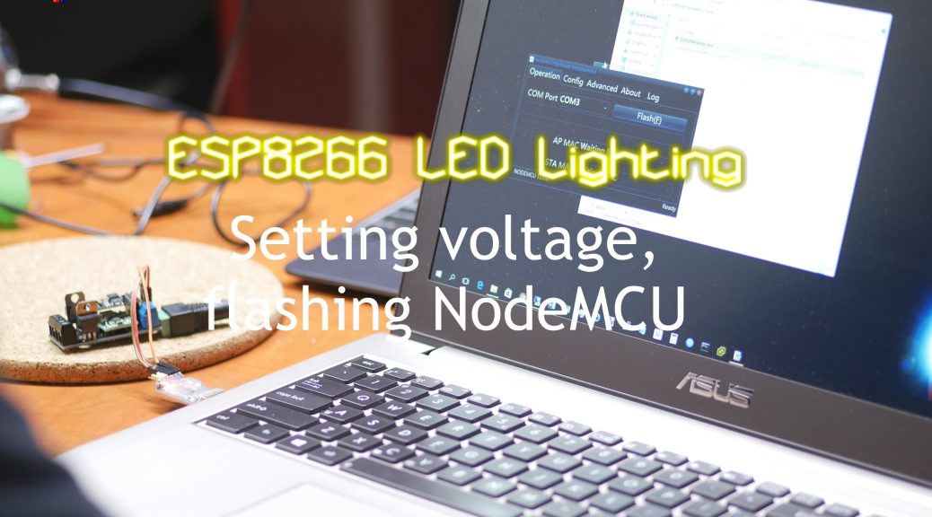
Once that is done, plug the serial converter into your laptop and check which COM port it creates. Start the NodeMCU flasher (included in the archive downloadable below) and select this COM port.
On the second tab select the NodeMCU firmware that is included as a file in the archive. One that is done, return to the first tab and hit the “flash” button.
If everything is connected correctly two MAC addresses should appear and the ESP8266 will be flashed!
Not always that easy
For some reason, the serial connection can sometimes be a bit unstable or not work at all. Try it a few times and if it doesn’t want to work, unplug everything and do it again. If it still doesn’t work, try some new cables or maybe use a different USB-to-serial module to see if it might work better. I have sometimes spent 20 minutes or so trying to get it to work to give up and start over 10 minutes later and re-wire everything to have it just work.
![Angry-Meme-02[1]](https://blog.quindorian.org/wp-content/uploads/2016/09/Angry-Meme-021-1024x640.jpg)
Workshop archive
I recently did a workshop on CampZone (Greatest vacation ever!) and have the workshop files available for download. It includes everything you need including flasher, firmware, program, etc.
![zip-file[1]](https://blog.quindorian.org/wp-content/uploads/2016/09/zip-file1-300x298.png)
Conclusion
Ok, that’s it! You now have the QuinLED all put together, set to the right voltage and the ESP8266 working and running NodeMCU! Remember, do not use the resistors, they are broken in the current version of QuinLED.
That means in the next video I will show you how to program QuinLED and actually make the light change using your computer!
Hi There,
My compliments on the work you’re doing!
I’m having an issue with programming:
The flash tool cant find the esp. When I disconnect the 3.3 volt to the CH_PD pin the esp starts flikkering blue but the tool still can’t find it.
I tried everything but cant get it to work.
– got 3 different programmers
– got a few esp modules
– tried different power supplies
– soldered a new board
– different wiring
Do you have any suggestions left?
Hey Wessel,
I think you bumped into the same “issue” that I had. Did you use the jumpers on the 2 pairs of connectors between the mosfets? after I did that, I had to re-insert the serial converter and it instantly started flashing
regards,
Henk
Hi Henk,
Eventually is was a combination of problems, wrong drivers faulty wiring etc. And during these fault I swapped the rx-tx signals, so when I thought everything was fixed and it still didn’t work I still had the TX on TX and RX on RX….
Quindor mentioned it in a mail, Thanks again 😉