
Over the last few years I’ve been gathering more and more equipment which supports Power over Ethernet such a access-points and the IP camera’s I’ve written about before.
I need something to power those POE devices! Most managable POE switches are quite expensive so I’ve been looking around for cheaper options and decided to order a “dumb” POE+ switch from China to test!

What for?
For my new home (which I’m currently designing and hope to start building soon) I’m going to use up to 4 Ubiquiti UAPAC access-points and 2 to 4 IP camera’s. At most that would mean 8 passive POE injectors/adapters in my 19″ rack. That won’t look good, or be pratical at all.
My options
I looked at getting a managed switch, but these easily start above $400 if you want something manageable with a decent power budget. So I was getting ready to spend the money on it and Zyxel seemed to have the best offering with their GS1900-24HP it offered 24 Gigabit POE+ ports with a total power budget of 170w.
But upon looking further and and debating getting 2 managed Gigabit POE switches with 8 ports, etc. etc. I found that you can buy unmanaged Gigabit POE+ switch for quite a lot less!
My test switch
Each switch has 4 Gigabit POE+ and 4 Gigabit ports. That makes 8 ports in total. Each POE+ port has an individual power budget of 30w. According to the specefications the switch can deliver about 72w of total power, so you can’t load all 4 ports to the full 30w!
The included power adapter is 48v and 2A that would make the total power available 96w! But, adjusting that down to about 85% it comes down to 81w of realistically usable power. I do not know if the power supply is the limiting factor or that the POE intelligence in the switch is actually a limiting factor.
In the manual it is written that if the switch would run out of power to provide it will start shutting down POE to port 4 first, then 3, etc. to remain within it’s intended power budget. The mentioned 72w of power available is very decent for 4 ports!
–update
I was able to find a specification sheet for the add-in POE+ board! You can find the specifications in this PDF.
The switching chip used is currently unknown to me but I expect it to be a cheap Realtek or something alike. Those are now dirt cheap and have been non-blocking in throughput for a while now so I think it’s safe to assume this switch also has a non-blocking throughput design. It employs the store-and-forward switching method as most switches do now a days.
Sadly the switch does not have a rackmount option available but it does have “rackmount” screws in the front so I’m going to see if I can devise a mount myself.
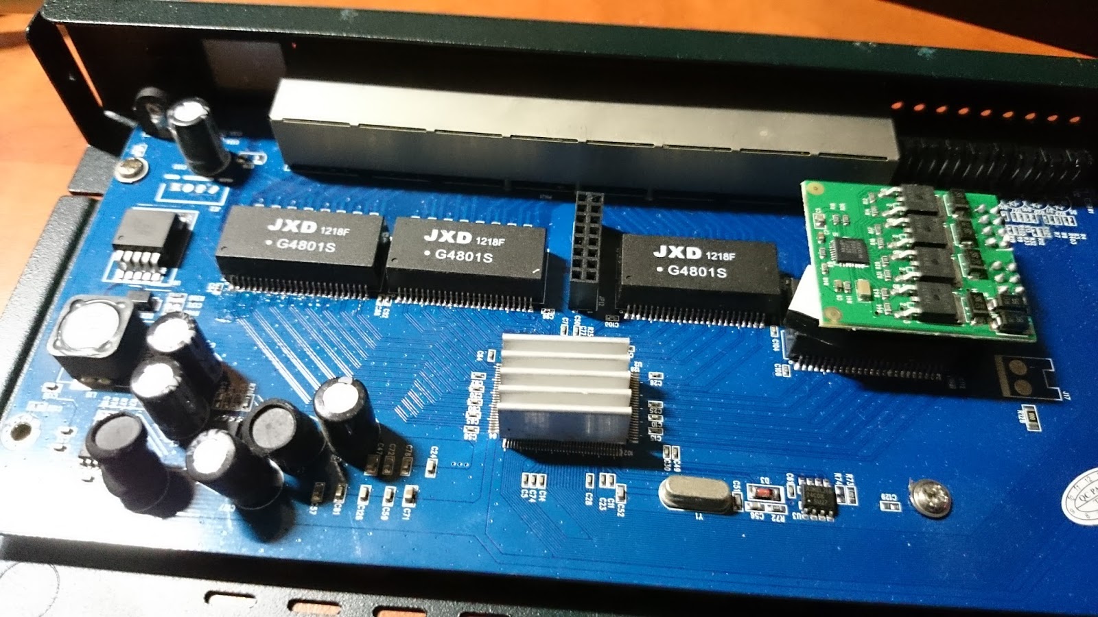
The website of XTDP-link does not list the exact model I have, but I think it’s because this switch can be sold in a 4xPOE+ or 8xPOE+ configuration. As the photos show one of the power board sockets has not been filled in my version and that’s why mine only has 4xPOE+ ports.
Tests
I also did some POE tests and took some wattage measurements. Keep in mind that spec sheets will always state the maximum power draw the device can ask of the switch. Depending on usage, settings (radio power, etc.), connected clients, etc. power draw will vary.
The results I got where the following:
2.2w – Just the switch
6.6w – IP camera with IR off
10.6w – IP camera with IR on
10.8w – IP camera with IR on through 50m of cable
15w – UAP-ACv1 idle, no clients
15.4w – UAP-ACv1 idle, no clients through 50m of cable
20w – IP camera with IR off and UAP-ACv1 through 50m of cable
*If you want to know what the device is actually using you need to deduct the 2.2w the switch is using itself.
As you can see the wattage the devices use becomes a bit higher using 50m of cable but not by much. Also the devices use a lot less then what is stated on their spec sheet. If you average that out over the 4 ports I believe the 72w will be more then enough except for the most extreme situations.
The IP camera is 100Mbit device and connected very quickly. The UAP-ACv1 is a Gigabit device but also instantly activated it’s port and the software confirms it’s connected with 1Gbps.
Photos
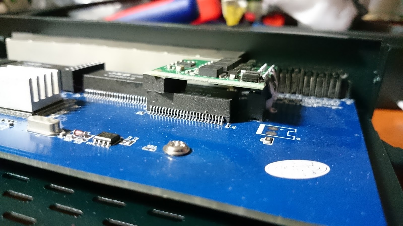
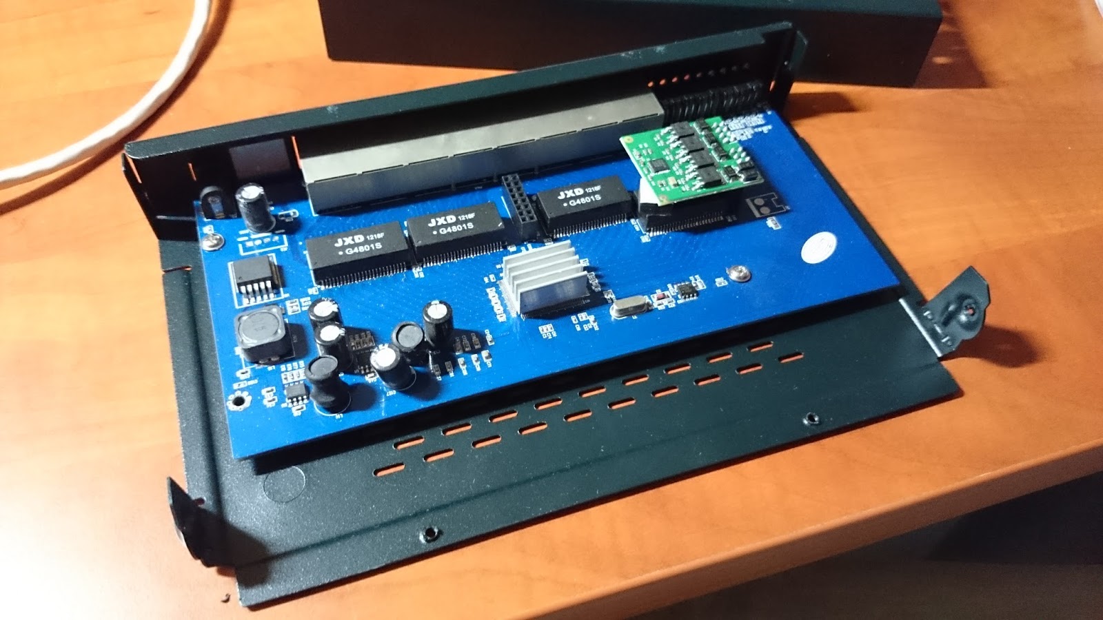 Internals exposed!
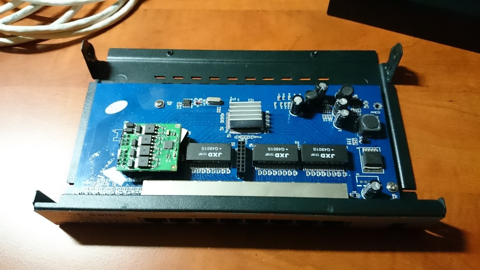 Different view
 Somebody payed great attention to detail here, supporting the board with a little squishy
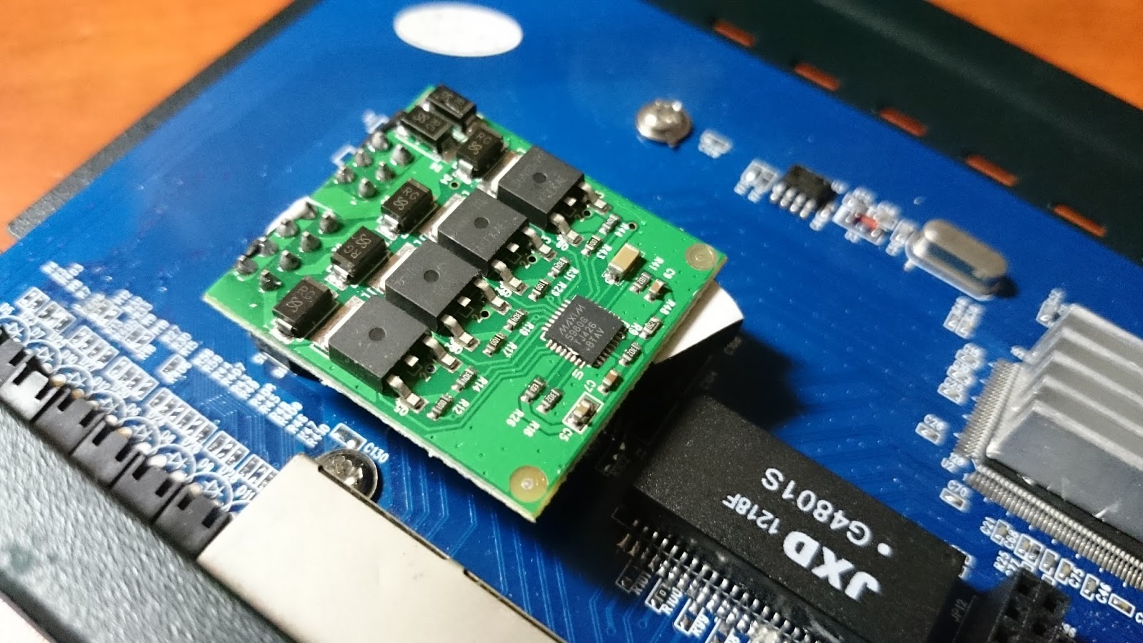 Detail of the suspected POE+ board
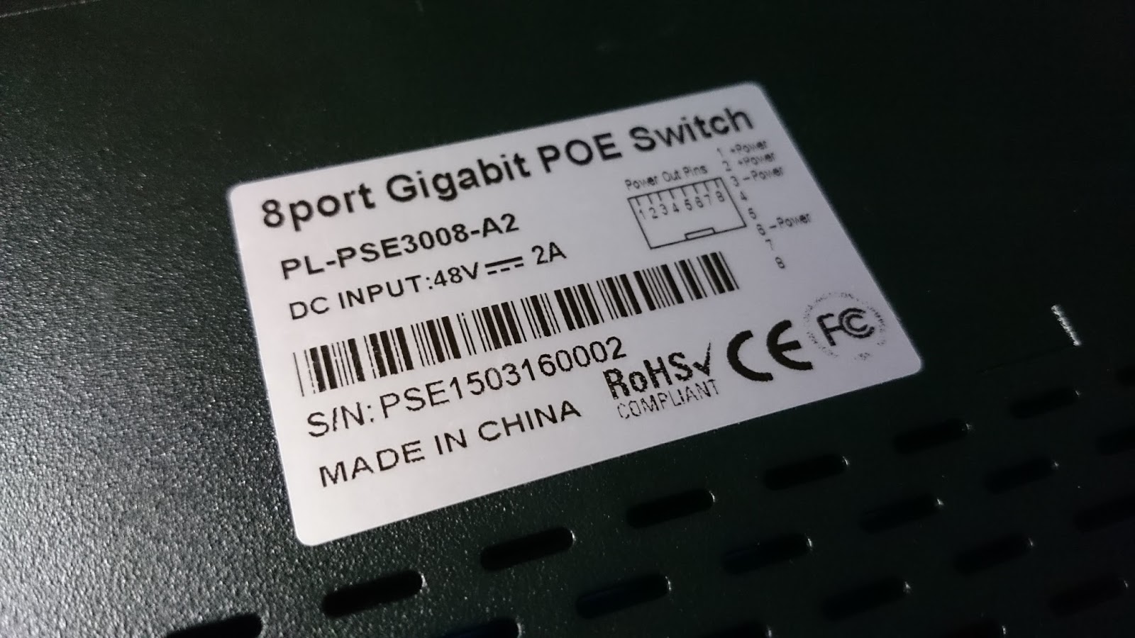
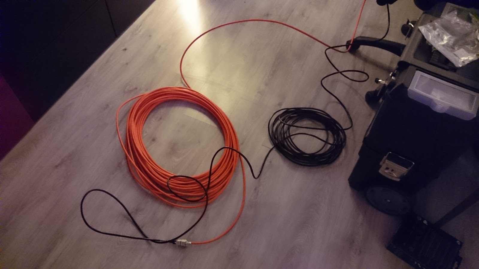
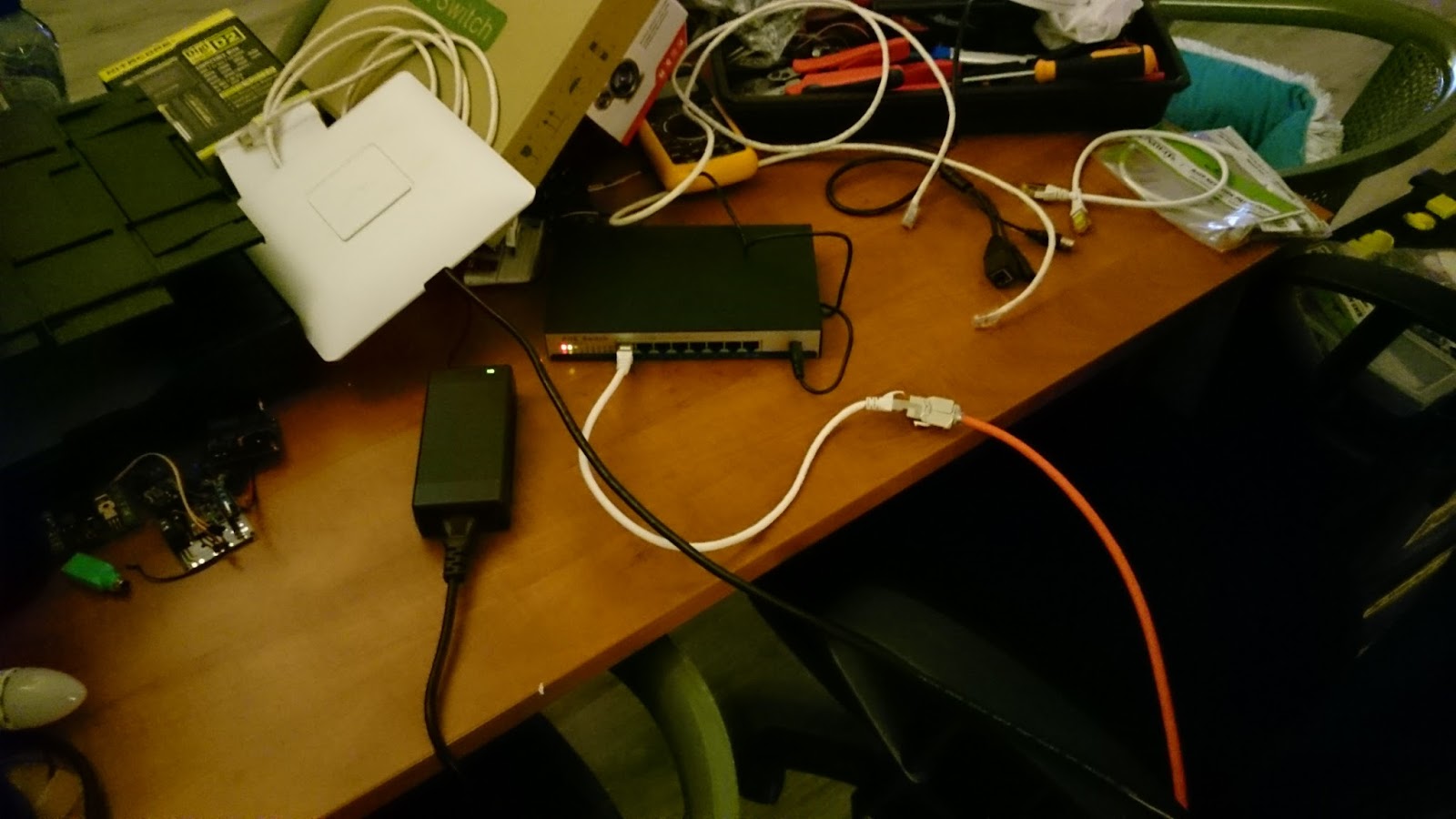
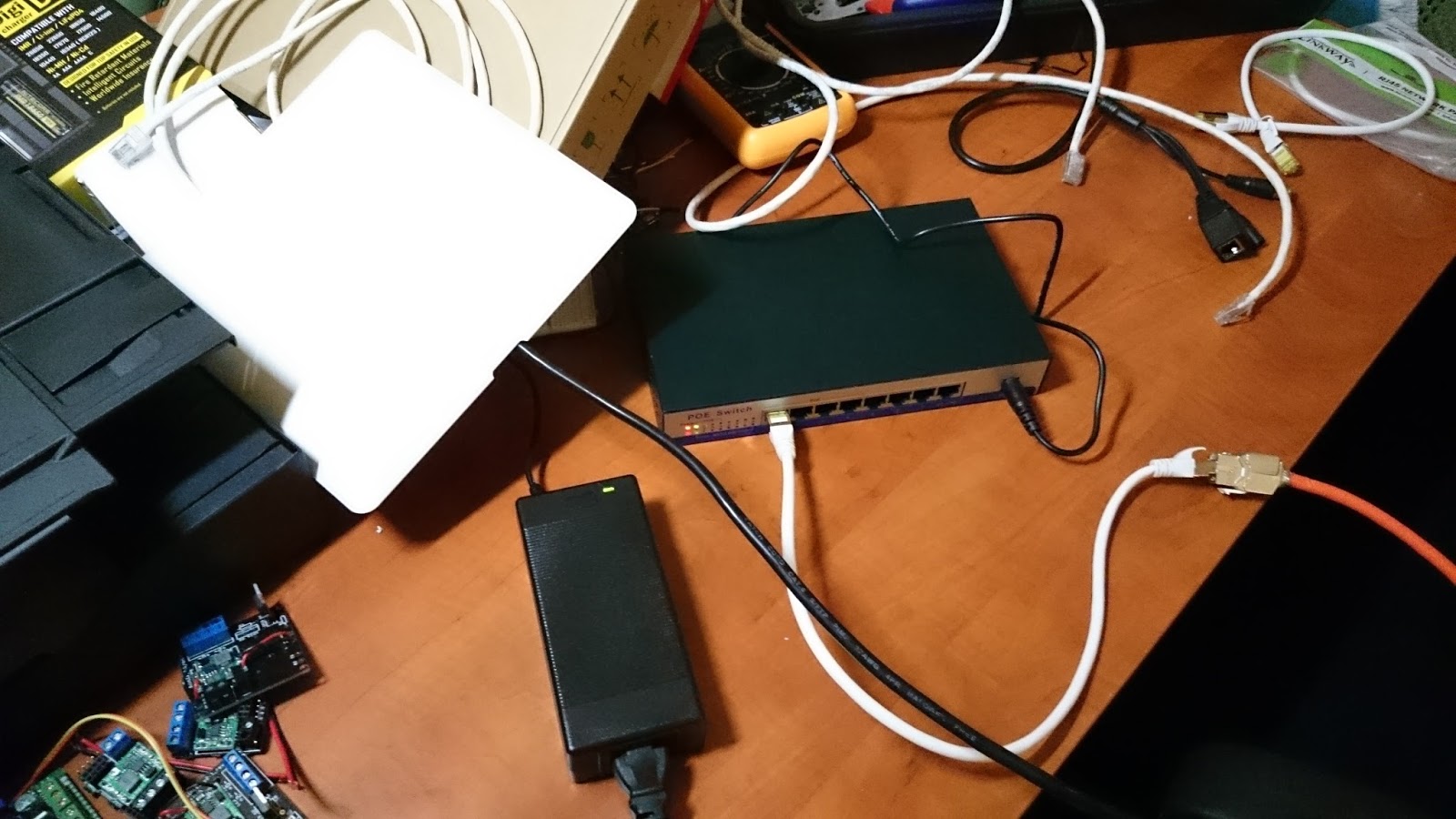 Another photo of the test setup. The big black brick is the power adapter
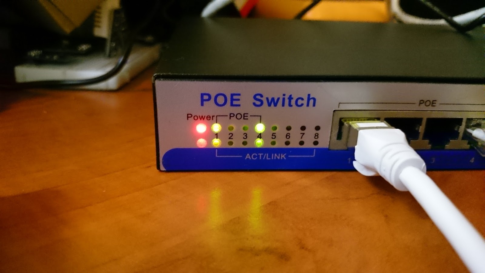
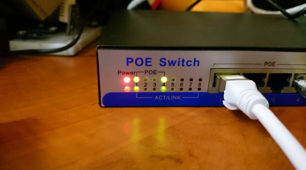
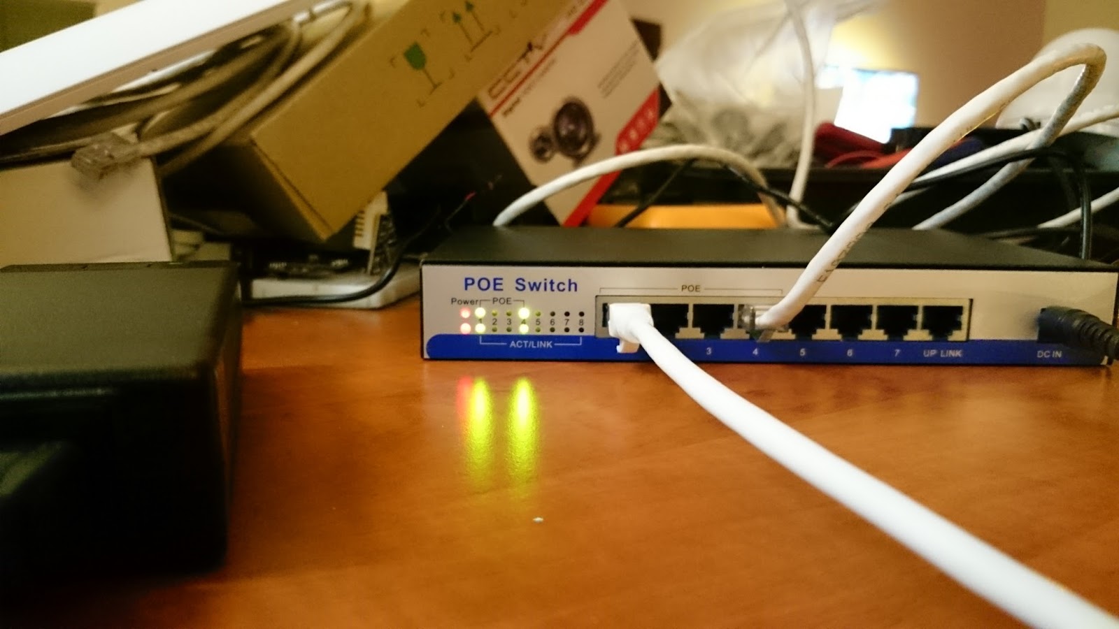 Switch during usage
Concluding remarks
I did a quick test to see how the switch reacts when VLAN’s are used and from what I could see if that it reacts the same as most other “dumb” switch I have used. It does nothing with the tags it just passes them on as it receives them. Perfect for me!
In my setup I will use 2 of these switches, one for all my access-points and one for all my IP camera’s.
! When plugging the power adapter in the switch there is a little spark. This happened to me a few times but didn’t cause a problem. To prevent this from happening plug the little plug into the switch first and the connect the adapter to the socket. To temporarily unplug you can also pull out the cable from the adapter to the socket. Then there won’t be a problem.