
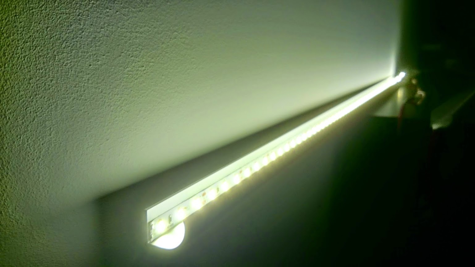
For a while now I’ve been working on building my own network controlled LED dimmer. I have sampeled some commercially available remotely controllable LED dimmers (DX.com models, AppLamp, Fibaro Z-wave, etc.) but all either lacked some fuctions or where WAY too expensive to rollout house wide. So, I decided to construct my own version! In the next few posts I will detail my efforts and explain in detail how to build the latest version! Read on!
This series has been rebooted
Please take a look at the following post to visit the new rebooted series and index of all posts: https://blog.quindorian.org/2016/07/esp8266-lighting-revisit-and-history-of-quinled.html/
Open on YouTube and select 1080p
My first try at building a network controlled LED dimmer started a few months ago. I’ve been toying with LED strips for several years now using (mostly Chinese) LED controllers. RGB is ok, but nice lighting in my house I focus on the softer and warmer Warm White LED’ s. So RGB will not be a part of these articles, I might make a separate set about them at some point!
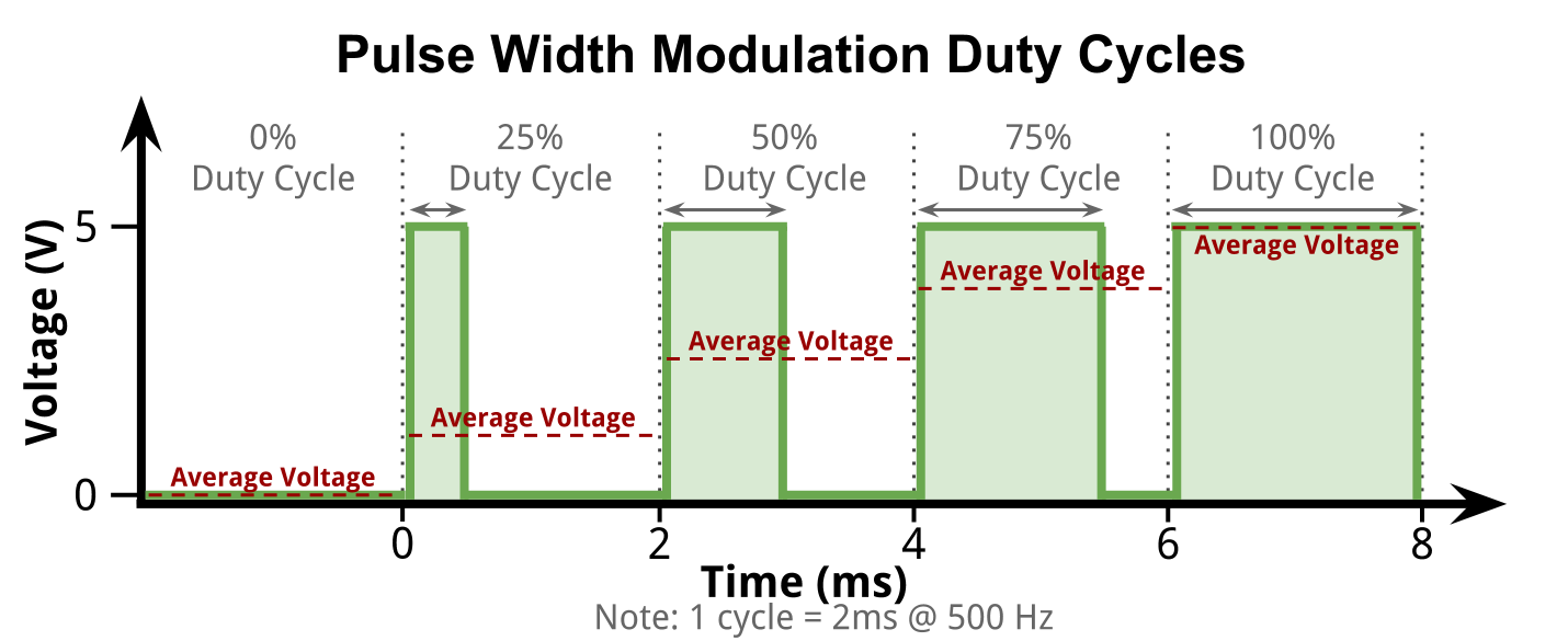
PWM Based dimming

Version v1.0 Arduino + RM04 based
What I will be describing in these articles will be QuinLED v2.1. QuinLED v1.0 was finished several months ago and has been working flawlessly since that time. It was based on using a (Chinese version) Arduino Nano v3 combined with a RM04 WiFi-to-serial module. I was about ready to ‘mass’ produce this version but then the ESP8266 suddenly popped up on the internet. It had some big promises on what it could do but mostly importantly, it’s price.

Cost saving potential!
The v1.0 version costed around 23$ to assemble. That means custom PCB, voltage converter, Arduino Nano, RM04 WiFi module, block terminals, 2 mosfets and some wiring. The v2.1 version shares much of these components just the Arduino Nano and the RM04 WiFi module are replaced with the ESP8266 ESP-01 module. A Chinese Arduino Nano v3 costs around 4$ and the RM04 can be found for around 12$. Making the total for just those two components cost around 16$. The shocker, the ESP8266 cost around 3$ and should be able to do the same functions! That would make a total module cost me around 10$ total! That might not seem huge, but it still allows you to make almost 2,5 v2.1 module for the price of 1 of the v1.0 version!
That was too good to pass up so I bought some of the modules and started working on getting the same functionality working. In a nutshell that functionality is basically building a LED PWM dimmer controllable with Domoticz (My Domotica software of choice). Everything else (how this is accomplished) was not as much important, although I have a preference for it working over my existing WiFi network and not some other protocol or RF, etc.
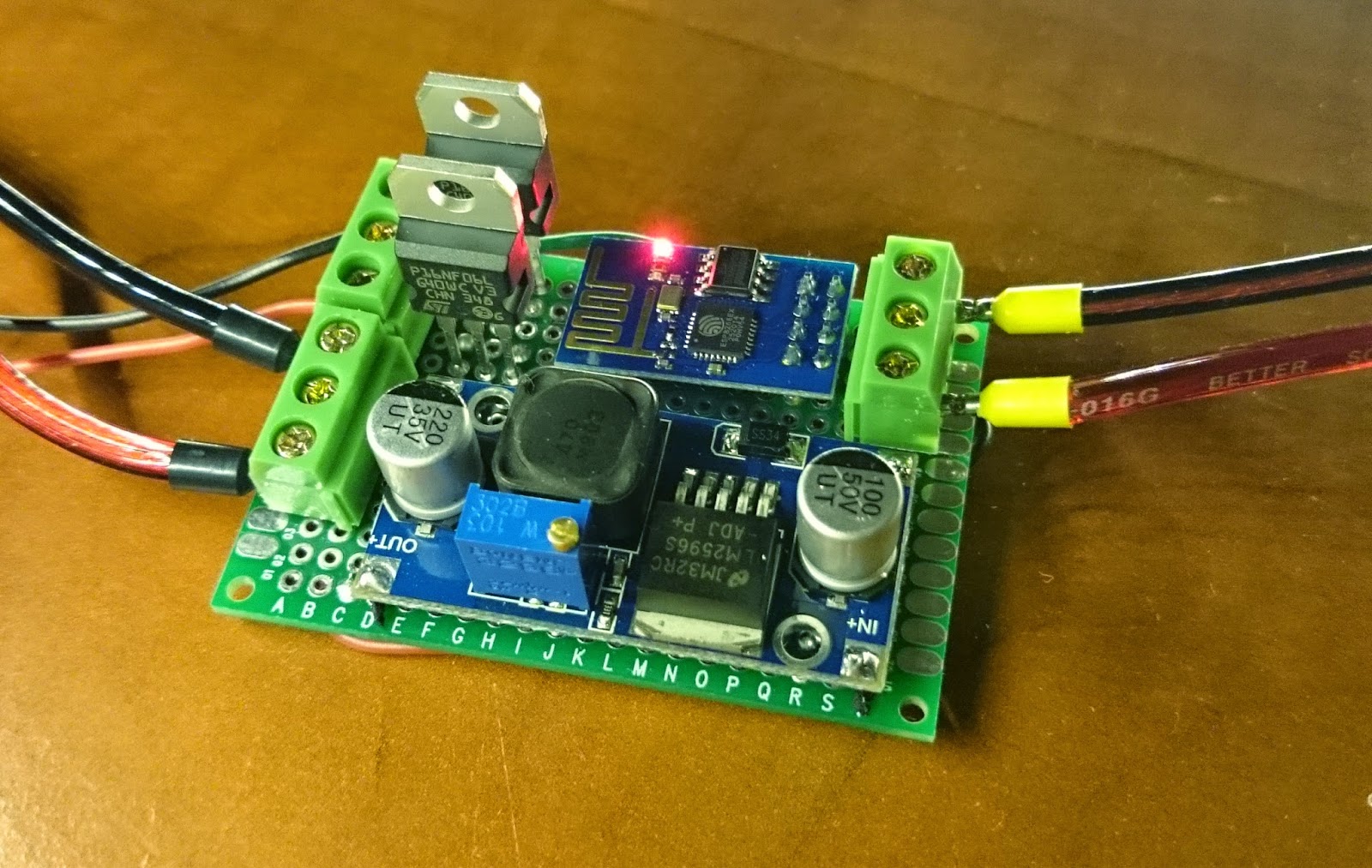
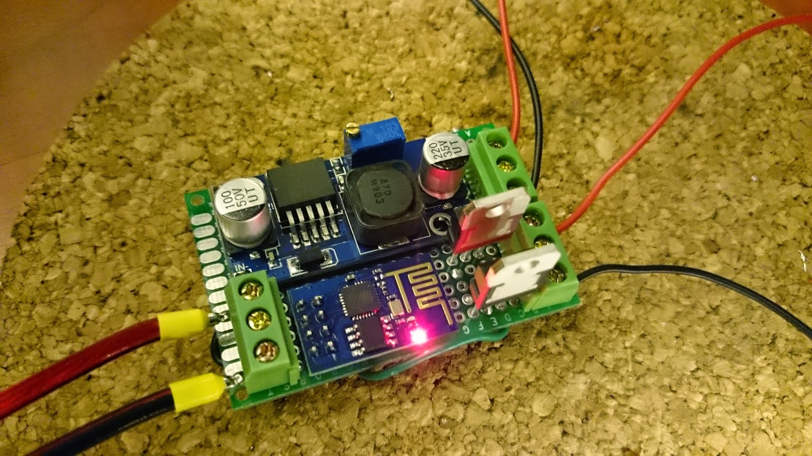
Version v2.1 ESP8266 ESP-01 based soldered!
Since a few days I have finished my ‘solid’ prototype of this v2.1 version and I have sent my custom PCB to http://dirtypcbs.com/ to get them made for me. I should have those in a few weeks. If those work out, I will post the schematics so you can have them made yourself if you so desire!
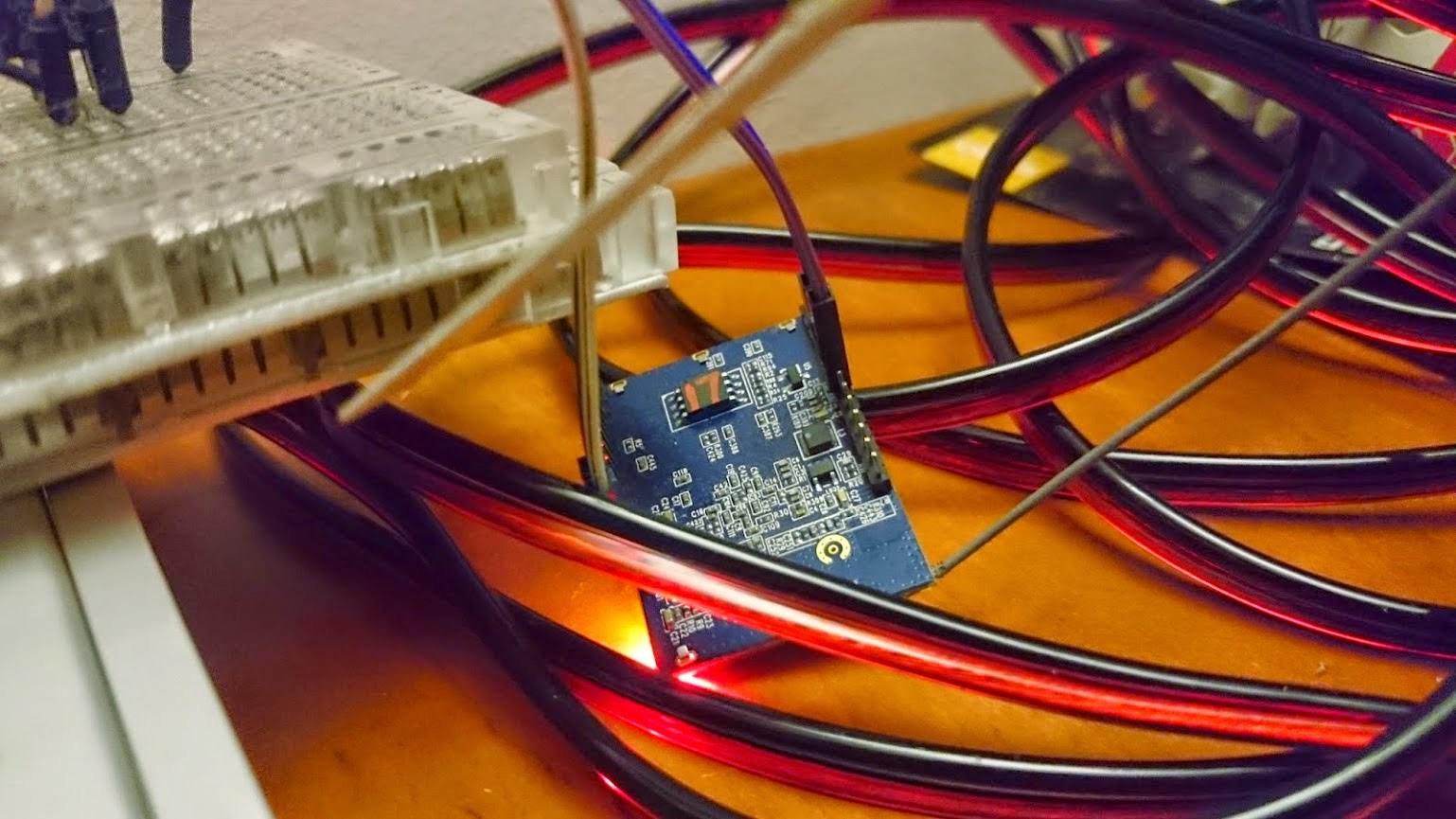
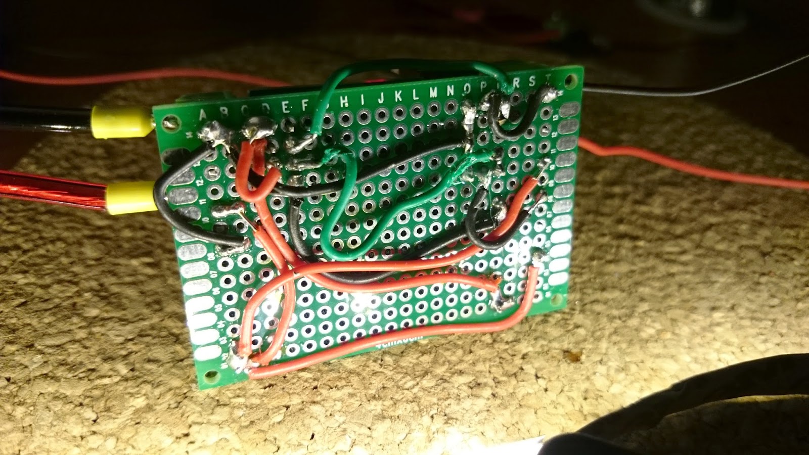
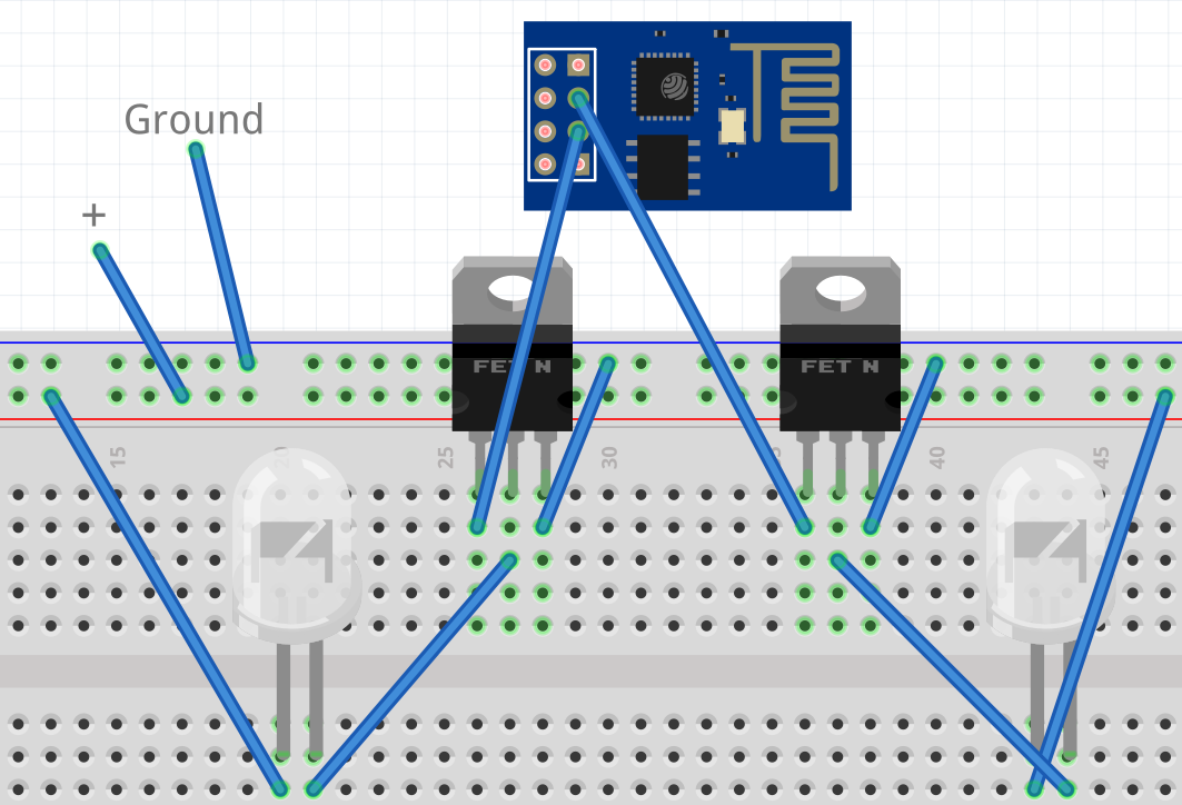 |
| Connections layed out on a breadboard |
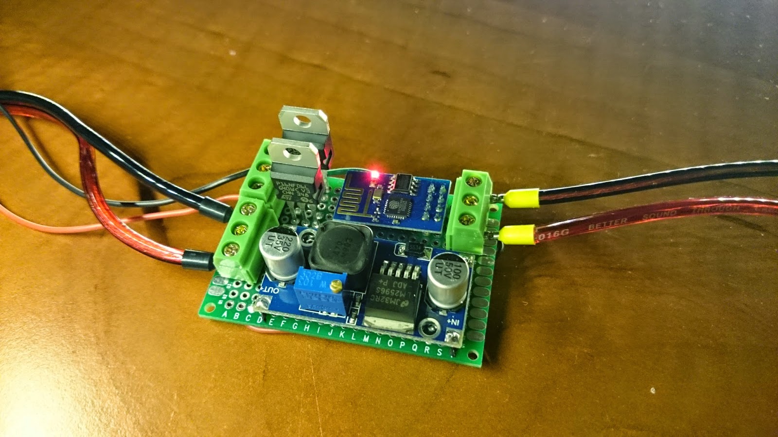
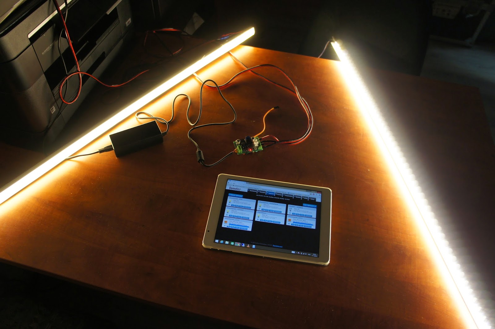 |
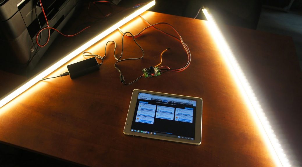
| The completed setup, controlling the LED strips from Domoticz |
V2.1 uses the NodeMCU firmware on an ESP8266 chip in specific the ESP-01 module. The NodeMCU firmware makes the module programmable with LUA, a high-level ‘easy’ programming language. Within this I make it join my wireless network and open a TCP port. Over this TCP port I send some recognizable text which the module reacts to and automatically dims to that light intensity. A special desire I had was to always have the LEDs fade and not just jump between certain values. In the current version that works on a very basic level, it always does so one step at a time with the time always the same between the steps, although that works, visually a more logarithmic or time based approach would be better. But that’s something for a newer software version. 😉
I guess that’s it for the first article. In the second article I will list all parts I have used and where I sourced them. Next up, all the hardware I used and where to buy it yourself!
As always, comments and tips are welcome and appreciated!
Have you noticed any periodic flicker on your PWM output when the duty cycle is consistent?
Hello sir,
I have ESP8266 circuit and wants to use this as a light dimmer. How can i setup this as a light dimmer.
I will appreciate any help.
Thanks in advance
Hi Mohd,
Your in luck, there are 8 blog posts detailing everything you need to know on how to do this! Everything should be there.
Kind regards,
Quindor
Hi Quindor
Thanks for sharing your great work..
Is the code available to download ? I'd like to try this out
Thanks
Chris
do you think, can we replace MOSFET with some TRIAK to control 230V lights? any diagram?
Thanks for sharing 🙂
Hi!
Can be used more dimming modules to control a lot of bulbs in the house?
Thank you
Z
Hi!
Can be used more dimming modules to control a lot of bulbs in the house?
Thank you
Z
I notice that you are not using any resistors. Is this due to using a MOSFETs and not needing the resistor on the base pin of a transistor?
Secondly you have two MOSFETs. Because you use White only led strips that have a 12v wire and a signal wire does your setup just allow you to run two independent strips at the same time?
Lastly. If the design of the v2 board was changed to accomodate rgb strips it would need 3 MOSFETs and at least an esp-03. Do you think it could still be made to fit on a small sized board like you have? Possibly mount the DC to DC converter underneath the board to allow the extra room on top for the extra pins of the ESP and extra MOSFET driver?
Hi,
I’ve followed this tutorial, but i get flicker in my led even at 1KHz pwm, and even with duty cycle fully on. What can be happening? i’ve used irf540N cause i did not found your mosfetr.
Yeah, sad to say but it’s the MOSFETs. The EPS8266 has 3.3v GPIO pins and the MOSFETs you used require around 4.0 volt to make them work correctly (even more so probably). Changing the MOSFETs for a type that has a “Gate Threshold Voltage” below 3.3v will do the trick.
If you want to test, you can give the ESP8266 more voltage (like 4.5v) and you should see the strip get brighter and stof flickering. This will rapidly kill your ESP8266 though!