This post will describe the hardware you need to build your own WiFi controllable LED dimmer! This post will list what you need, why and where I bought it from!
I have added a zip file with the Fritzing files and gerber files you can use to make your own boards. I have also included a link to dirty PCB’s where you can order them directly and help me out a little bit!
–update 2015-04-09
I have created a v2 of my board. It is optimized in every way and a LOT smaller then the original. I advise everyone who is looking at creating a board to make the v2 version! You can find it here, including an order link and a Fritizing design if you wish to re-use it.
–update 2016-07-06
I tried to update most links so that you can fill your shopping carts easily!
Make sure to check the updated hardware list post. The hardware in this post is mostly NOT maintained!
Chinese Retailers
Since a few years I have been a fan of sourcing small electronic supplies in China. Although not always ‘as good’ as the products you can buy here in the store, they are often not quite bad either and very much sufficient for the task. The price difference is the biggest reason though, it’s just unbeatable, whatever way you look at it.
The main sources for me are http://www.dx.com (Dealextreme) and since recent years http://www.aliexpress.com (Largest Internet retailer in the world). Especially the last one takes some skill to navigate, but when you get the hang of it, it can even be a bargain over Dealextreme!
Aliexpress buyer protection system is unmatched. They have their own payment processor and the seller only gets their money if you acknowledge you have received your package in good order. If you do not, or something else is wrong with it, they see no money, so the seller is very motivated to send you a correctly working product!
So, very much recommended. A word of warning though, use some common sense when buying in China… too good to be true? Well, it probably is. Things work differently over there, there are no copyright laws for instance. See a MicroSD card of 128GB for 11$? Well, it’s 100% fake.
All the items listed in this post have been linked to the respective stores I bought them from and I had a positive experience with!
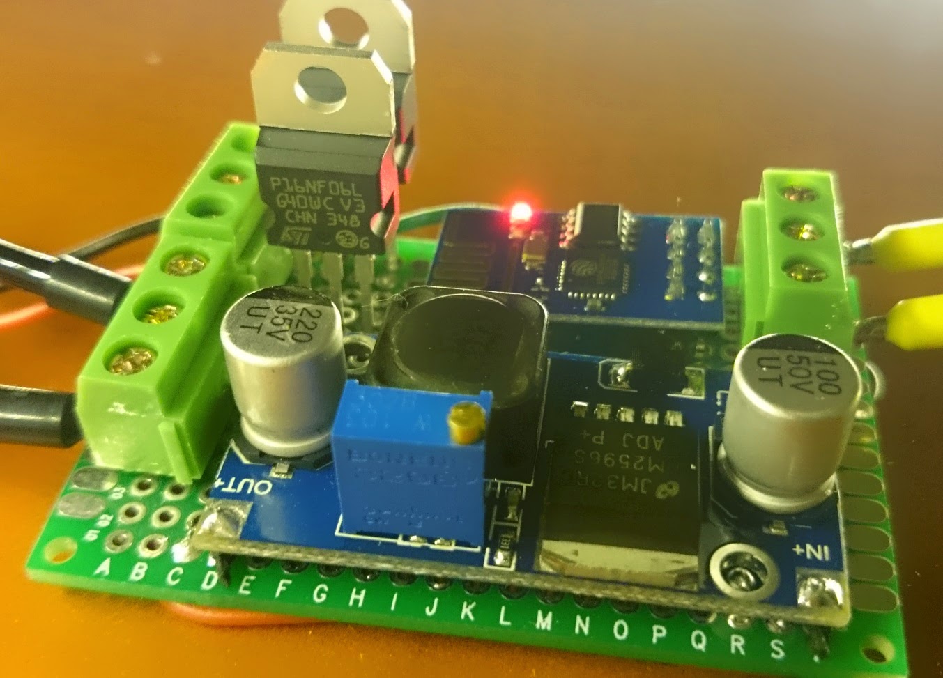
Components for the ESP8266 soldered prototype board
The assembled soldered prototype board
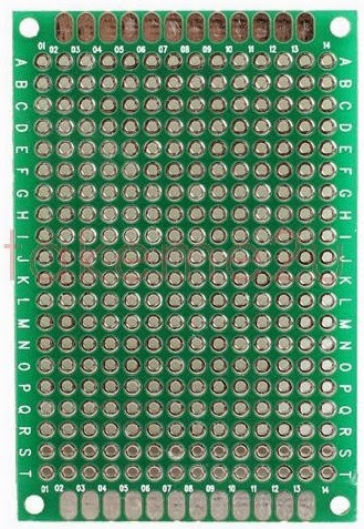
1. 0,30$ A solder ‘breadboard’. The one I used is the following: Aliexpress Link
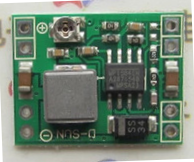
2a. 0,93$ A voltage converter (from 12v to 3.3v). The one I used is the following: Aliexpress Link. It has a little screw to adjust the voltage to the desired output (do this BEFORE hooking it up!)
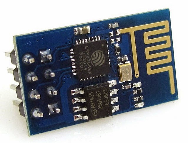
3. 2,71$ A ESP8266 ESP-01 module. The one I used is the following: Aliexpress Link
4. 0,25$ Some terminal blocks. The one I used is the following: Aliexpress Link
*These do NOT fit well into the solder breadboard, I made them work but the pins are a bit too wide, try and find better one’s! I have since bought some blocks that do fit the board well. You can find them here, or check out the section below where I have 3 colors listed.
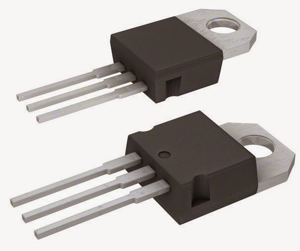
5. 2,00$ Two MOSFET’s. The ones I used are type PWRMOS 60V 16A STP16NF06L [STM] and I bought them here: Conrad webshop (It seems you can find them cheaper on Aliexpress now). Look out when shopping for these MOSFETs, I often receive wrong types that only trigger at or above 5v and you need to them trigger under 3v!
6. 0,15$ Solid core wires for the soldered connections (Also work in normal breadboards!). The one I used comes from: Eleshop link
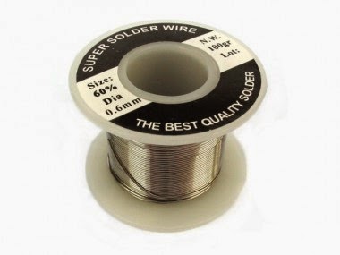
7. 0,10$ Solder tin to link everything together. The one I used comes from: Eleshop link
That brings the grand total of all the material used to aprox ~6,50$! That’s even better then I thought myself. 😉
In the future, when I receive my PCB design from http://dirtypcbs.com the above price will change a little bit. The board will then cost 1,40$ a piece but since I don’t need so much wire and solder anymore total price should be around 8$ total. The amount of time to make the board (and how it will look) will decrease from a few hours to 30 minutes though. So well worth it. 😉
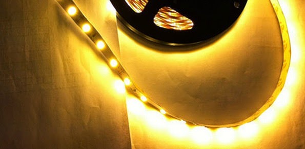
8. 7,90$ The LED strip I use are 5630 (chip size) 5m non-waterproof 12v LED strips. They use about 10 watt per meter at 100% brightness and provide ample light. They are a warm-warm white (~2800K) instead of warm white which you most often get (~3200K) giving it a nice and yellowish warm white light. It took me a while to find a strip I liked because the all give you different colors. This one is the best I have been able to find! You can find them on Aliexpress here. Be sure to specify you wish to the 2800K-3000K version otherwise you will get the normal ~3200K warm white version! A Tip! Feed your LED strips at both ends of the strip for longer lengths (1.5m+). When using long LED strips something called voltage drop occurs. The copper that inside of the PCB of the LED strip is very minimal and thin. Over the length of the cable it will lose it’s power and thus decrease the brightness of the LED’s at that part. I have seen it as bad as a 5 meter strip having half the brightness at the end of the strip as in the beginning. That is VERY noticeable.
The solution? Feed your LED strips on both sides. This way the total voltage throughout the cable becomes much more stable which means the light the LED’s produce is much more consistent throughout the cable, even with 5m of length. Worst case this means pulling a thicker 1.5mm (14 to 15 AWG) copper cable besides it, but the results will be much more pleasing!
9. ~12$ You will need a 12v power supply. This will power the whole board and it’s components + the LED strip itself. The ESP8266 can only take 3.3v (although mine wants 5v it seems?) and we regulate this down with the above mentioned voltage converter. You can regulate the converter using the little screw on top of the blue tower, use a multi-meter to measure it and set it to the correct output BEFORE you hook the rest up!
5 meters of LED strip will use about 50w to 60w 12v when properly fed.
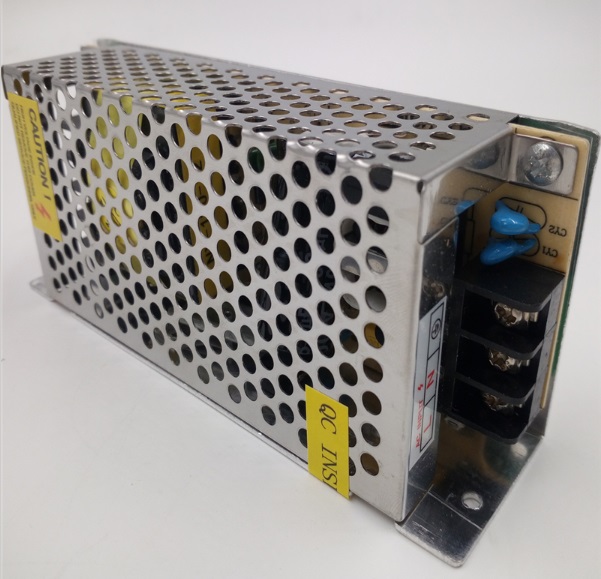
I often get my power supplies from Aliexpress and although some have failed, most have worked perfectly fine for the last few years. These slim 120 watt power supplies should be sufficient to run the strips. I always advise to overprovision the power supplies so you will not be running them at 100% load at any point.
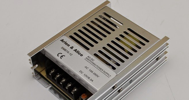
For smaller requirements I tend to use these 12v 70w versions or even these 12v 36w for if I’m only driving 2 to 3 meters max! It depends on you usage. Limiting the amperage effectively limits max brightness so a low wattage power supply does not have to be a bad thing. I do tend to keep myself to the general rule of always staying in between 20% and 80% of continues usage of a power supply though. Any lower or higher will drastically lower efficiency and lifetime while increasing heat output!
MOSFET?
A MOSFET is basically a switch and a power amplifier. It has 3 pins. A gate, drain and source. The drain goes to your LED’s and provides the switched signal, the source provides your constant voltage (or ground in our case). The gate controls when power flows through the MOSFET and when it does not, it gets hooked up to the PWM pins on your Microcontroller (ESP8266 or Arduino).
My selected MOSFET is the STP16NF06L, you can find a PDF datasheet here.
There are several important factors which this MOSFET has to confirm to.
1. Voltage range
The MOSFET has to be able to handle the voltage your giving it. In our case the selected MOSFET can handle 60V max, we are using 12V so safe
2. Amperage constant/max
The MOSFET can handle op to 16A of flow with an outside temperature of around 25 degrees Celsius. If that temperature reaches 100 degrees Celsius it can only sustain 11A of flow. Should be plenty. 😉
3. Switching Speed
The switching speed determines how fast the MOSFET can raise and lower it’s voltage on the drain pin, thus letting the LED light up. Although these specs are a bit hard to read for me too, the MOSFET I have selected (STP16NF06L) seems to work very well.
Itss spec sheet lists the following:
Raise time + turn-on delay: 47 ns
Fall time + Turn off delay: 32,5 ns
So one pulse would take around 79,5ns.
Since 1 milisecond (our switching rate) is 1000000ns, we should be VERY safe in our switching rate. 😉
4. Gate input voltage range
The input voltage determines how much voltage is needed to fully open the MOSFET output/drain. In our selected MOSFET this range is from a min of 1v to a max of 2.5v, our 3.3v from the ESP8266 should be more then sufficient.
The way I interpret this is that it states which voltage is needed to fully open the drain, not what it can sustain at maximum. I’ve had 5v on one of these for a while now (using the Arduino v1.0) and it has caused no problems.
Wiring Diagram
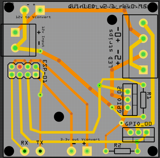
I will provide a better wiring diagram later on. For now please take a look at the PCB design I made. You should be able to figure out all the connections and replicate those in your soldered design! The PCB design will become available when I have tested (and maybe revised) it!
First PCB design, click to enlage
I also made a breadboard overview of how to connect everything. Hopefully that explains it a little bit better.
Basically, the + is connected right from the 12v power supply to the LED’s. The minus or ground runs from the ESP8266 to the gate pin of the MOSFET. Ground is directly connected to the source pin and then the middle drain pin is connected to the LED.
That way when the gate receives an open pulse, it opens the source to the drain and the LED gives light.
(The ESP8266 takes 3.3v (it will run briefly on 5v but that will kill it after longer usage!) but sure NOT to put 12v on it!)
Tools needed
Besides needing components, you also need some tools to accomplish the task!
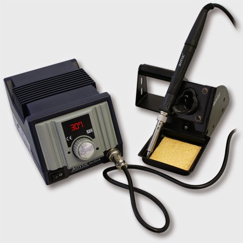
1. A soldering iron or soldering station. I used to have a crappy soldering iron from Dealextreme but recently I threw it away and bought a decent soldering station with digital temperature readout. BIG improvement. I got mine from Eleshop. They sell this 70w station for a very very decent price. A model without the digital readout costs even less!
2. A third hand. This tiny little gadget that holds your project for you so you can use the tin in one hand and the soldering iron in the other. Just makes life easier. Mine has a built-in magnifying glass to check your work with a little LED light. I recommend getting one!
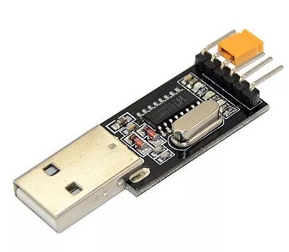
3. 5,29$ You will need a USB to Serial connection to firmware flash and program the ESP-01 module. I recommend getting something like this on Aliexpress. It’s important that it has a 3.3v and 5v output capability. Also remember to buy the needed Mini-USB cable if you don’t have one.
Alternatively you can also get a CH340G type which has a USB port on it.
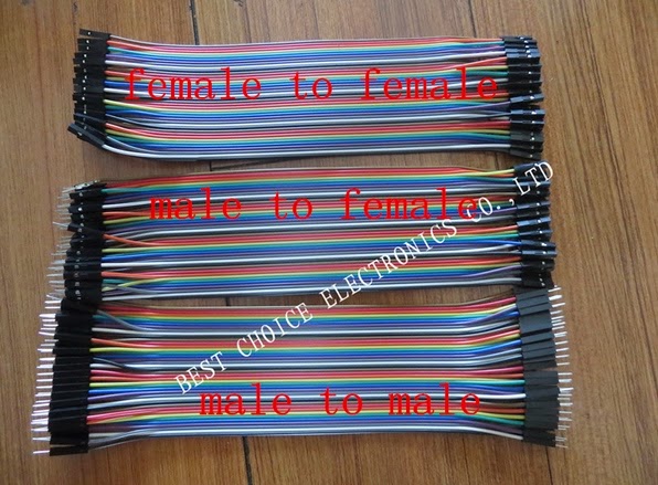
4. 3,85$ Get some dupont cables. This cables come in three different forms and they can help you make easy and temporary connections. They are also often used on breadboard’s to make connections. The female variant fit perfectly on the pins of the ESP-01 and of the serial board making it very easy to get started! I recommend getting a set like this on Aliexpress
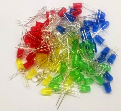
5. 3,90$ To help test your setup it might be handy to have some LED’s which can run directly from the ESP-01’s power. I use some small multicolor LED’s for this which can be connected directly into a female dupont cable. Very handy and it simulates what is going to happen with a mosfet and LED strip connected perfectly! You can get them on Aliexpress here
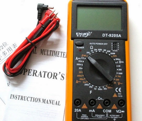
6. 10,12$ A multi-meter. To measure the output of your power supply, voltage converter and to check your soldered circuits. I have one from a few years back but in my experience cheap one’s from Aliexpress seem to work fine for basic tasks!
7. Crimping tools and plugs! Wire crimping allows you to use multi-strand wire in terminal more easily, they also ensure a good connection and are often used in the automotive world to prevent vibrations from loosening cable connections.
First, I recommend getting the following:
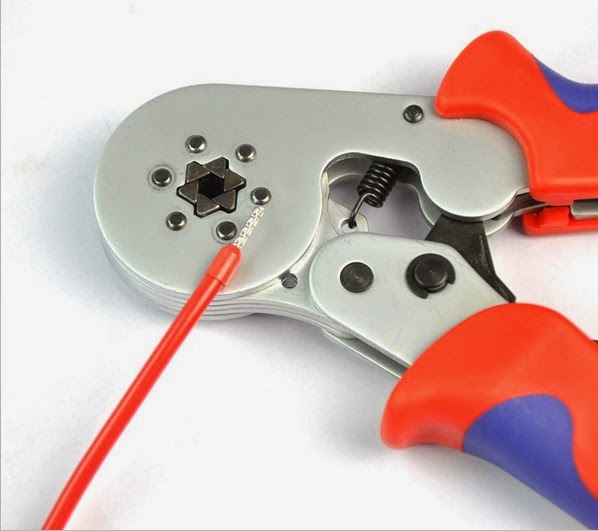
Crimping tool
Box with ferrules
The first is the crimping tool, it pushes the metal together in a hexagonal pattern to provide ample grip and a solid connection between wire and terminal. The second is a box is ferrules of smaller sizes. Since we are not walking with a giant amount of Amp’s, these ferrules should be well suited for the job at hand.
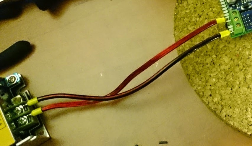
In my work you can see them being used here:
12v power to board, no messy wire strands and a secure connection
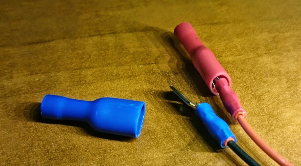
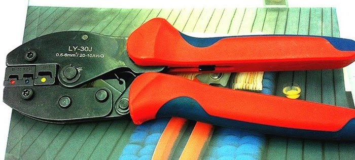
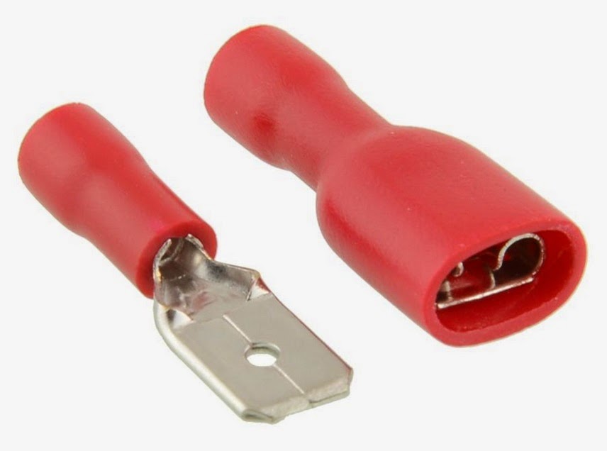
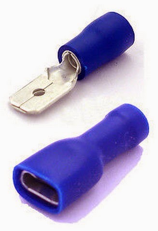
Second, I recommend getting some connecting ferrules as pictured below. They allow you to make an isolated detachable connection. This requires a different tool then before.
Secure cable connection and detachable
For this you will need a tool with the right inlay bit and the plugs. Officially the plugs are color coded per size (red, then blue then yellow) for different size of cables, I like to use them also to differentiate plus and minus. To fill the plugs up I use the above crimping tool first and then crimp that connector inside of this one making it a very strong and sturdy connection.
You then also need the plugs. The red and blue (bigger) should be able to accommodate all of your 12v work. If you wish to use it for bigger stuff too, also get a set of the yellow one’s. I very much prefer the fully insulated versions as shown!
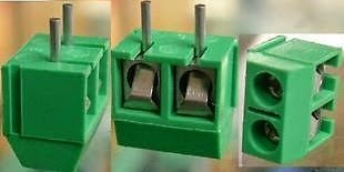
Terminal blocks are little connector terminals which you can use to connect your wires to your board. The one’s in the picture where of the wrong kind but I didn’t have any other lying around. I got new one’s and these work perfectly! The spacing of these should fit breadboards, prototype boards (Like I used in this example) and PCB’s.
You can find the three different colors I bought here: Green 0,08$ , Blue 0,07$
Terminal blocks
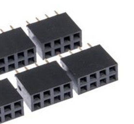
And I think with that you are all set! Most of you will probably already own a soldering iron and some wire, plugs and maybe even a soldering breadboard. Or might want to use different components, that’s the fun of this hobby, everyone can use the stuff they will best suited for it! You think you need/want a different MOSFET? Awesome, go for it! 😉 9. ~0,08$ 2×4 Pins Double Row Female Straight Header Pitch Socket You can use these pin headers to solder onto your board so you can still easily remove the ESP-01 to do flashing or something else with it!
I have created a v2 of my board. It is optimized in every way and a LOT smaller then the original. I advise everyone who is looking at creating a board to make the v2 version! You can find it here, including an order link and a Fritizing design if you wish to re-use it.
I soldered another board yesterday and it fully worked on both channels. That means now I have more working PCB’s then not working PCB’s, so I feel confident enough to share the design. It’s a bit of a clunky design and v2 will be a lot better, but also more complex (using ESP-12). If you are going with my blog posts and the components listed there, this should work quite well.
A word of warning though, I give no guarantee this will work in your case and that the design of this board is perfect. It certainly is not and the way the voltage converter is connected with little wires is beyond clunky… It works though, no problem!