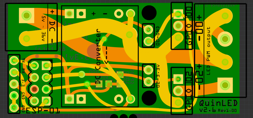
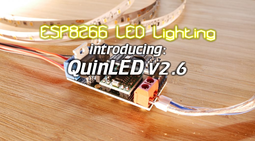
It’s been a long time in the making but I’ve finally put the final touches on my newest revision of QuinLED! This makes it version 2.6 rev 1.00. Let’s check it out!
This post is part of a series
The index for this series can be found here.
Video about the new board
To test the new design I decided to make a video about me soldering and testing one. It’s about 30 minutes long, but I show you some tips & tricks and take you along through the whole process. This video doesn’t replace the soldering tutorial perse but some of you might find it interesting anyway.
DirtyPCB Direct Order link
Most of you will want to use the direct DirtyPCB order link. This gets you 10x 5×5 boards which in turn are 20 QuinLED dimmers. With each having 2 channels that would make a total of 40 channels!
Click here to order the boards. Doing so also gives me a small kickback so that’s appreciated!
I often get asked if I don’t have a few boards to spare, no, no I don’t. I often use my boards in my own projects, throughout my home and also during workshops, so nothing to spare.
Still, I understand that you probably won’t need 20 boards, but then again, looking at the price it’s only ~12$ to get the boards anyway, just don’t use them all or give them to a friend! The other components you need all come in lower amounts (such as 5) so I think that would be the minimum to build.
Fritzing source files
As always if you’d like to order the boards somewhere else, you can download the fritzing files and gerber files here.
If you decide to use the files to make your own work, that’s fine but a link back to here would be appreciated!

Conclusion
This board design will be the last one for a while. As far as I’ve been able to test, everything is working now and as far as the design goes everything seems to be in the right spot and the trace thickness is better then ever allowing the highest power to run through them of any of my designs.


Hello!
Why did you use different mosfets in this version?
They have the same properties I just have several different versions of them but they are basically the same. I haven’t been able to find any difference between them so that’s good. I noticed on some boards that there would be more whining noise then on others so I wondered if it was the MOSFET type. But as long as the MOSFET confirms to the specifications (see my previous posts about that) you should be good to go!
p.s. Especially the gate activation voltage should be below 3.3v, often they are spec’ced for 5v which would be fine for an Arduino just not an ESP8266 as I’m using here. Chinese suppliers often get that wrong. 🙁
Be sure to get some with a low Rds, since this largely determines the amps it can handle before getting too hot 🙂
Ah yes, very true!
In the dirtypcb link both boards work right? (missing trace fixed?)
Yes, the link that is up right now is the fixed version!
Hi!
I just bought a Osram Soleriq P13 COB LED and I remembered that you had some COB downlights. Can I run it of a boost converter with voltage set a bit under the forward voltage?
In theory, if you can use constant voltage (instead of constant current) to drive the COB LED you should be able to put PWM on that signal and dim the COB LED with that. That is exactly what I did with mine.
Measure the voltage of the power supply that comes with it (It will have a range but function at a certain voltage during operation) and then just get a different (constant voltage) power supply to put out that voltage. Most frame power supplies (Like the Mean Well’s I’m using) have a voltage adjustment range. So I use a 36v power supply at 33.2v for my COB LEDs and it’s been working perfectly for me!
Hey, how can you put 36V to your QUINLED V2.6 PCB ? It should heat enormously?
can i use this, modified, to drive 1w or 3w power leds?
What’s changed in the new board version?
I believe I talk about that in the video and in this article?
But mainly it has an optimized layout, upped the power handling and the resistor implementation works if you want to use those.
Nice work! What are the dimensions of the assembled board?
One board is about 24mm in width and 50mm in length. Height is around 25mm to 30mm
I finally got around to properly testing some boards that I assembled earlier in the year, and wanted to control them via MQTT. I looked around and found that espurna would be ideal (having tested that with an Ai Light), so decided to try and get espurna working for the QuinLED. There were no code changes required thankfully, just some ‘header’ and config tweaks. It built fine, flashed fine (via serial and OTA), and worked fine.
I submitted a pull request and it’s been accepted into the dev branch of espurna, which might be useful to some readers who are looking for additional features.
See: https://bitbucket.org/xoseperez/espurna/pull-requests/35/support-for-quinled-26/diff
Love these boards 🙂
Wow that’s awesome, thnx for testing and all the work! Glad you like the boards. 😀
What kind of tweaks did you have to do? I’m trying to do the same thing but just can’t get it to flash.
Hi I have completed my quinled and it seams to work well except for that the 12V led striped are shining very poor. even when i use only one chanel. i can see that my input is 12V and when no led attached to the channel I get 12 V out. but when i connect a led stripe to one channel it drops to about 6-7V ( the other stays on 12V ) if I change the voltage on the voltage regulator it gets brighter but then my ESP will get higher Voltage and will be fried.
What do i do wrong?
regards
Yeah, you probably got sent wrong MOSFETs too. I keep changing the link to hopefully get a supplier which always sends out the right one’s but sadly, it’s hard. If you can source the MOSFETs locally which adhere to the 2.5v trigger voltage, it will certainly work! 🙂
Have you ever considered adding push button connection, so you would be able to also control them locally? I was working on similar design, but with buttons, then I stumbled on your great design. Just wondering how hard it would be to add button connection
This would indeed be a valuable addition. I’m myself planning such a mod but using a rotary encoder with (or without) click button functionality. Such a mod does however come with sacrifices. The ESP-01 has in its default state only two available GPIOs and both are used for the PWM dimmers in the QuinLED design. There is however a way out, as can be seen e.g., here: http://www.instructables.com/id/ESP8266-01-Building-Blocks-Unleash-2-Bonus-GPIO-Pi
The Serial communication of the ESP-01 can be disabled during normal operation to allow for 4 available GPIOs, all with PWM functionality!
I have constructed a prototype using ESPeasyMega (the testing variant) which has all software components you need and a prototype bord. On this board I have designed it with a rotary encoder to provide the dimmer functionality and the click button as on/off. However, this can easily be changed to provide two PWM dimmer channels instead and skip the click functionality.
The tradeoff is that such a board will not allow serial flashing of the connected ESP-01. I see this as acceptable because of 1. The ESPeasyMega has very good OTA firmware upgrades so for most scenarios this will not be needed and 2. The ESP-01 is easily detached to I will have a spare QuinLED 2.6 where I can do the flashing.
I have today ordered my first batch of QuinLED boards and will as soon as I have them sketch on the required modifications. If anyone is interested in contributing to this project, chime in! Any help is appreciated.
Awesome comment! I’d love to see the code when you have it, if it’s a good feature/addition I’ll do a dedicated blog post about it!
My boards just arrived today 🙂 Exactly 2 long months 😉
Thanks, thank you for sharing, my family is using, I can’t get your dimming firmware to access my home assistant, hope you see my message and thank you again. Life brings beauty!
Can we control the 220 V AC powered LED BULB?
Sorry no, not this way, I tend not to mess with AC.