
Sometimes you accumulate a lot of equipment in one spot that all runs on 12v. This can for instance be a rack with multiple switches and routers or, as in my case, 15 External Hard Drives, a USB HUB and some fans that all need 12v. To cut down on the clutter, let’s take out the 18 Adapters to run this and replace them with a single power supply.
Index
To make this article a bit easier to navigate here is an index to quickly skip to a part:
[To-Do]!
End Setup Goal
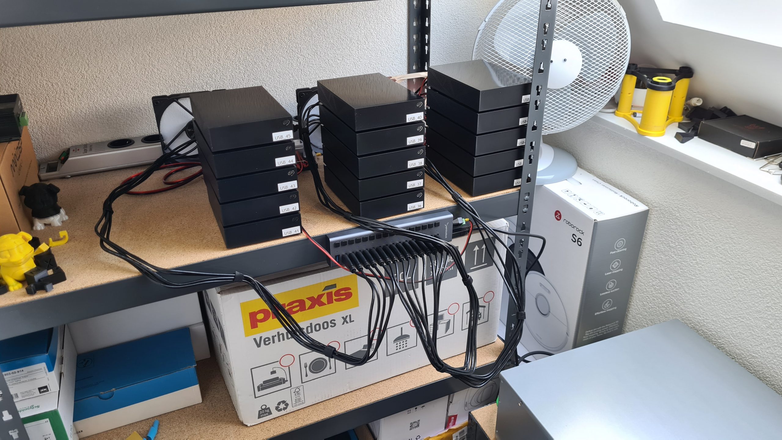
In my case I want to hook up:
- 15x 8TB External USB3 Seagate Expansion disk
- 1x 16 Port USB3 HUB
- 3x PC FAN
Normally this would use about 17 to 18 12v adapters requiring 3 large power bars and wires going everywhere. Even worse, the spacing of the power bars often can’t accommodate multiple adapters next to each other so it’s going to be even more of a mess.
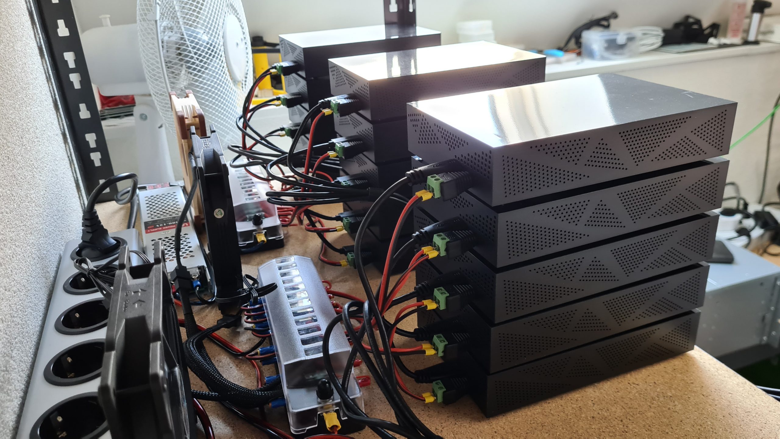
 Looking nice and tidy with all the custom cables
 Clean setup with all the changes!
What kind of Power Supply do you need? (Power draw calculations)
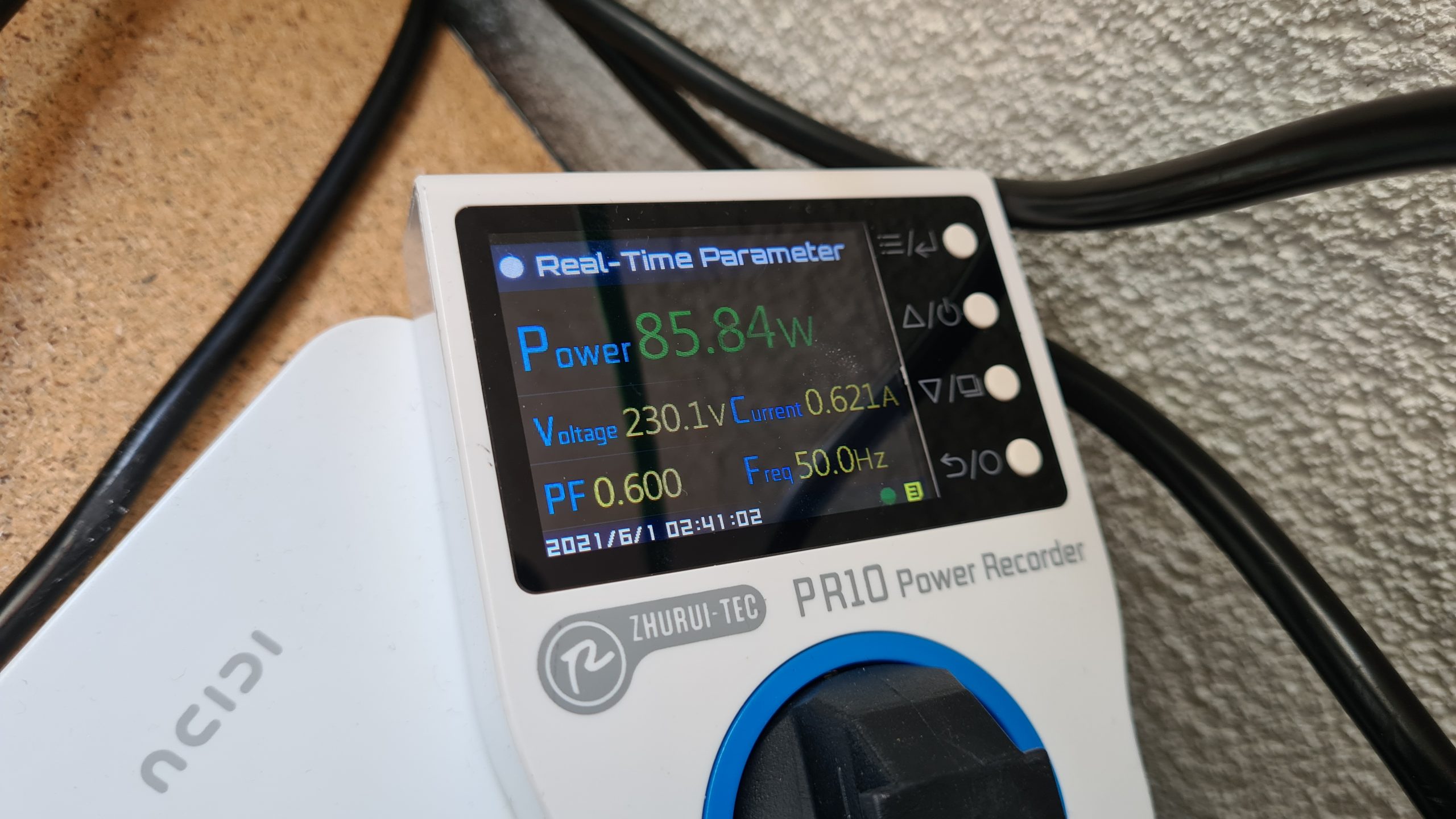
The total power draw of all of this is much less then you’d expect. A single disk uses about 10w-15w to start up and on average draws 5w while just running. The USB HUB also won’t draw too much power since we are only connecting self-powered devices and then fans generally only draw 2w to 3w max.
In total I generally see about 80w to 90w being used on average and during startup (everything at the same time) I see about 225w-250w AC side peak for a few seconds and then it quickly goes down again. This also forms the basis for using a 300w power supply. Although with these Seagate drives, they don’t power on without an active USB connection and since the used HUB has a on/off button per port, you could start them up individually if you wanted to.
For setups of different sizes you can scale the above numbers up or down using the per disk number in calculations.
Tools, Equipment and consumables
To do this project you are going to need various tools, equipment and consumables. Some you might have, some not, but they are all tools that I use very often doing these kind of projects or LED projects, etc.. I believe it’s always good to invest in some decent tools!
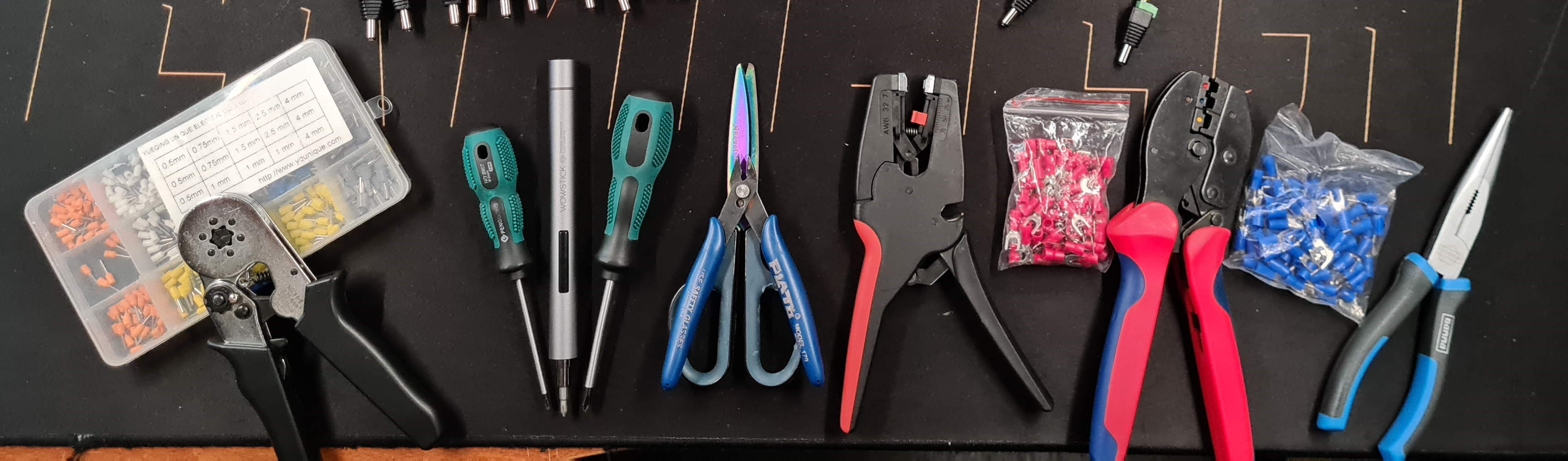
(All links below are affiliate links for Amazon, Aliexpress, Banggood and might earn me a small kickback for sending you)
Crimpers:
👉 Wire Ferrule Crimpers kit
👉 Connector Plug Crimpers
Wire:
👉 High Quality wire (all kinds of sizes)
👉 Fan Extension cables
Misc Equipment:
👉 Automatic Wire Stripper
👉 Wire Snips
👉 Pliers
👉 Screw driver set
👉 Electric screw driver
👉 PR-10C Power Meter
Fuse Boxes and Power Supply:
👉 12 position positive/negative fuse holder
👉 Good Quality fuses
👉 Decent Quality 230v AC 300w Power Supply (EU Local – Aliexpress only)
👉 Good Quality 200w Power Supply
Plugs:
👉 Screw in 5.5 x 2.5mm barrel plugs
! Often these are 5.5 x 2.1mm, those will not fit !
Computer Hardware:
👉 Chia Plotter hardware
👉 Recommended disks
👉 16 Port USB HUB
👉 Good Quality PC FAN
The Setup
The way this will all be connected together is as follows:
- AC power socket
- 12v 25Amp (300w) “Frame Style” Power Supply
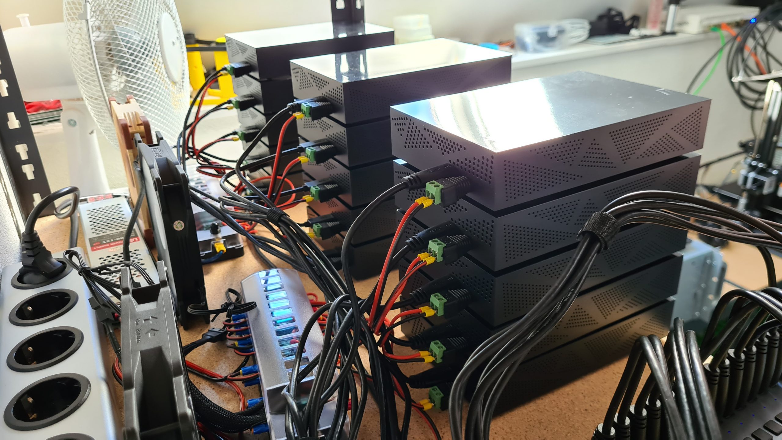
- 2x Fuse/Distribution box
- Cables towards HDDs, USB HUB, Fans
- 2x Fuse/Distribution box
- 12v 25Amp (300w) “Frame Style” Power Supply
This way all connections will be individually fused, so if a short happens on a cable or a failure occurs in one of the connected devices, it won’t take the rest with it but it will just pop the fuse for that port and the rest will keep functioning as normally.
This gives me a bit more piece of mind since I intend to have this running for the next few years. Using fuses certainly adds a bit of safety, personally I would not hook up 16+ devices to a single power supply otherwise!
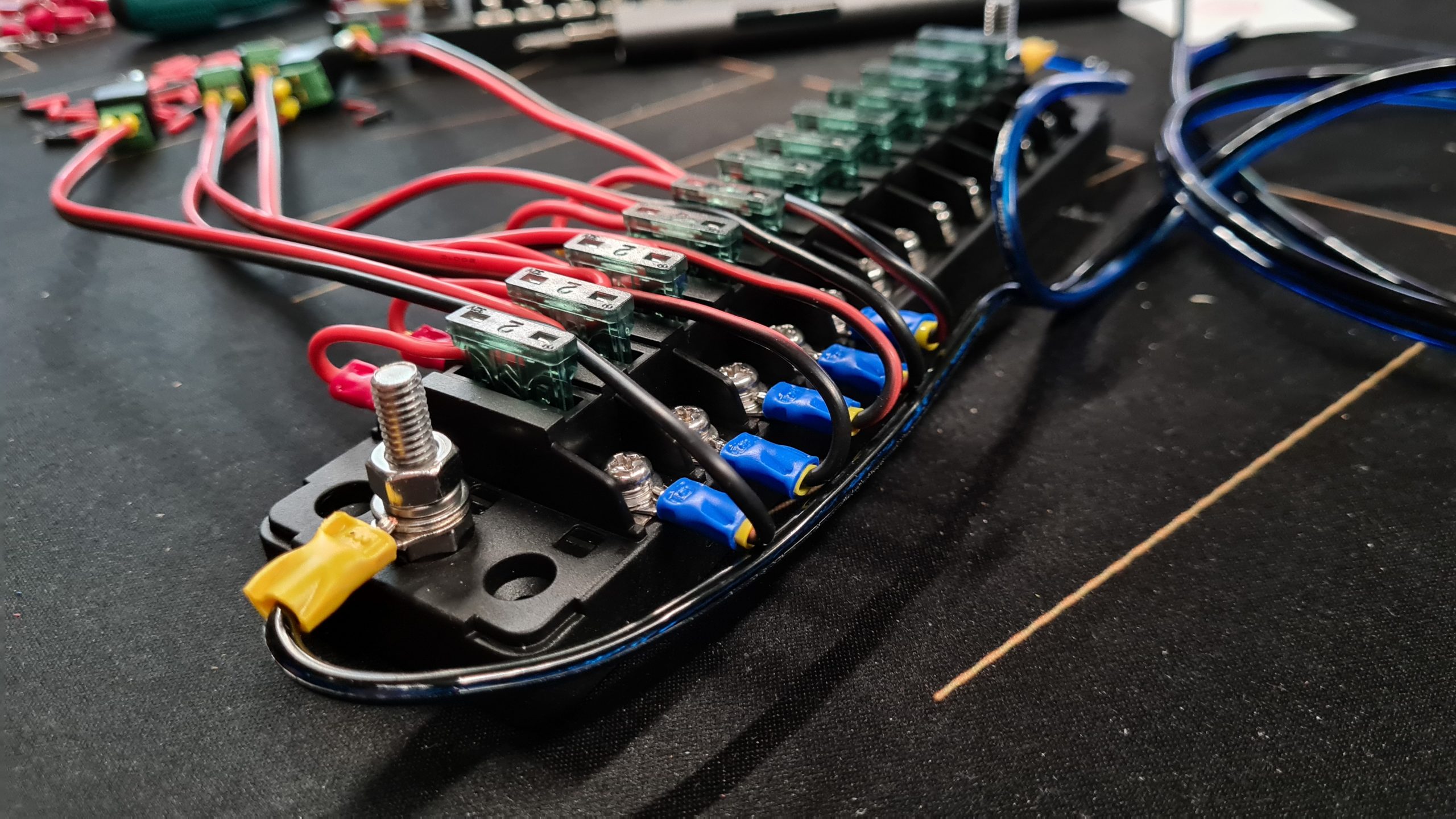
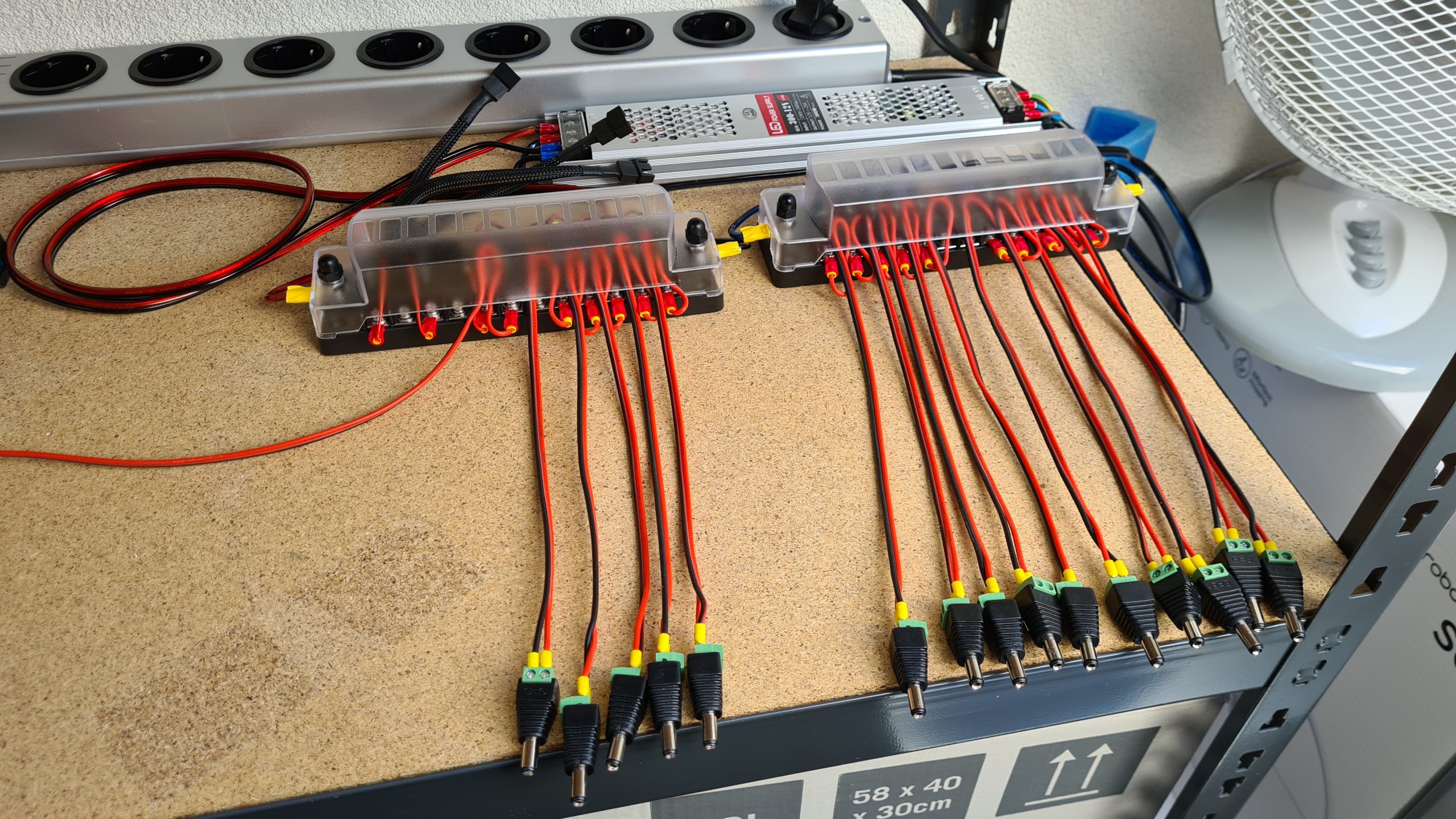
 Build in progress shot of hooking up the individual cables to the fuse/distribution block
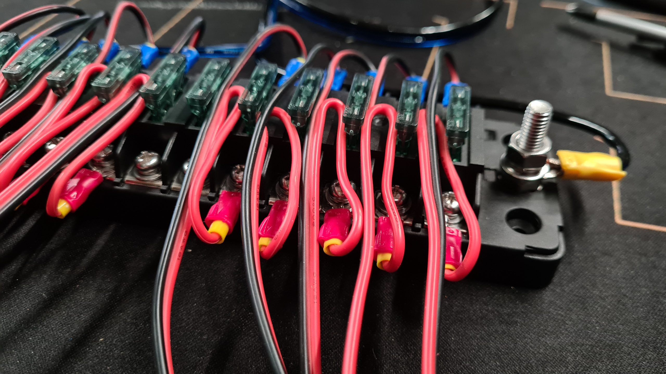
 End result of creating 10 individually fused cables!
Preparing the cables
To do this project right, you are going to need several of the tools listed above, in particular those are the ferrule and connector crimping tools. These help making strong and secure connections with stranded cable.
We’ve all been there, trying to attach stranded cable to a screw terminal and some of the “hairs” of the wire never go in, they stick out, easy to touch something else, all in all a bad experience.
Wire ferrules fix that and going beyond that using cable connectors (such as the fork connectors we’ll be using) provide a much better and secure solution making sure that when screwed down it will make good contact and stay there.
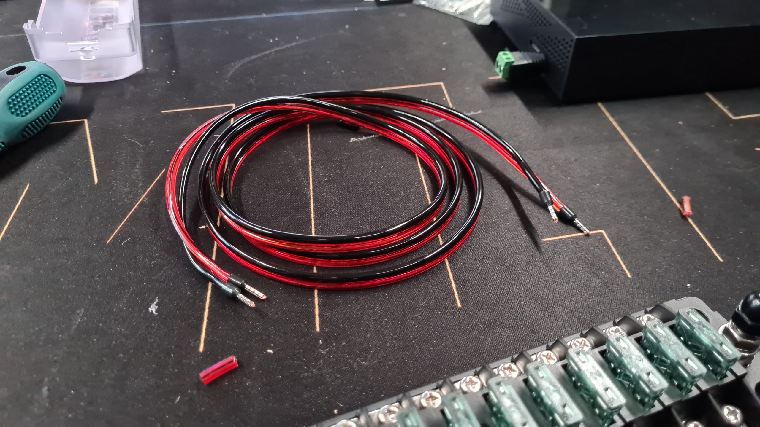
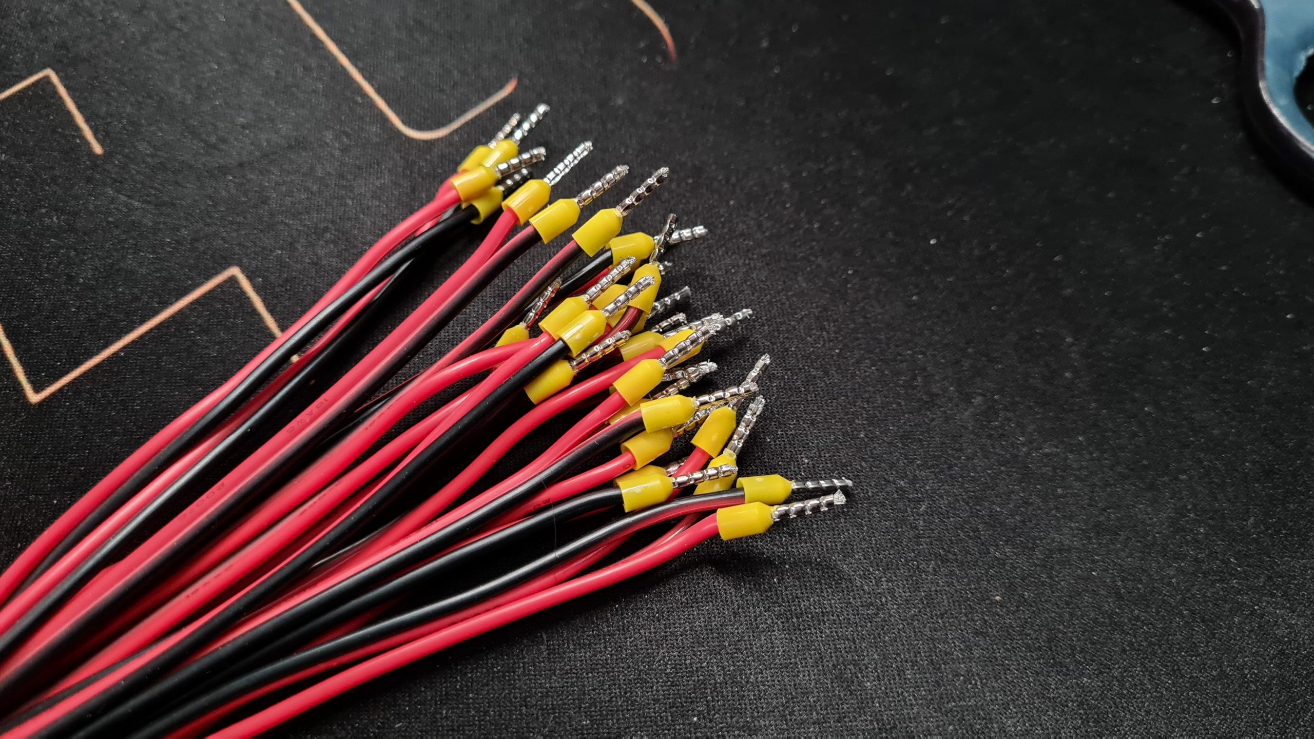
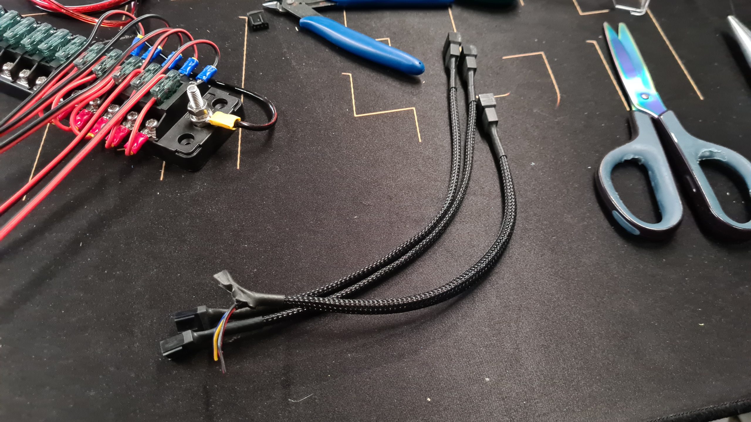
Step 1 – Cut your cables to length
Step 1 is cutting the cables to length, in my case I cut all cables going to external USB disks from the AWG18 silicone cable and made them about 15cm in length. The length you are going to need will depend on your setup, I’d try to keep them under 50cm if possible.
Do this 15x (for all the disks) and 1x (For the USB HUB).
Then we’re also going to needing 2x cables to connect the power supply to the Fuse/Distribution blocks. For this I used AWG15 cable and made them about 100cm each to have enough room to get these in the right position close to the drives.
 The AWG15 cable to hook up the fuse box (already with ferrules)
 All the AWG18 cables for the drives cut to length (already with ferrules on one side)
Step 2 – Add wire ferrules
Add wire ferrules to all ends of the cable. Yes, I use wire ferrules even for the cable ends that are going to be using a crimped on connector. I know this officially isn’t the right way to do it but in my experience I cannot get the cable connector to stay in place well without it. This might have something to do with the connectors I have or my crimping tool but still my reality. Since none of the connections are going to be running very high currents, I believe this to generally be fine and at least very securely attached.
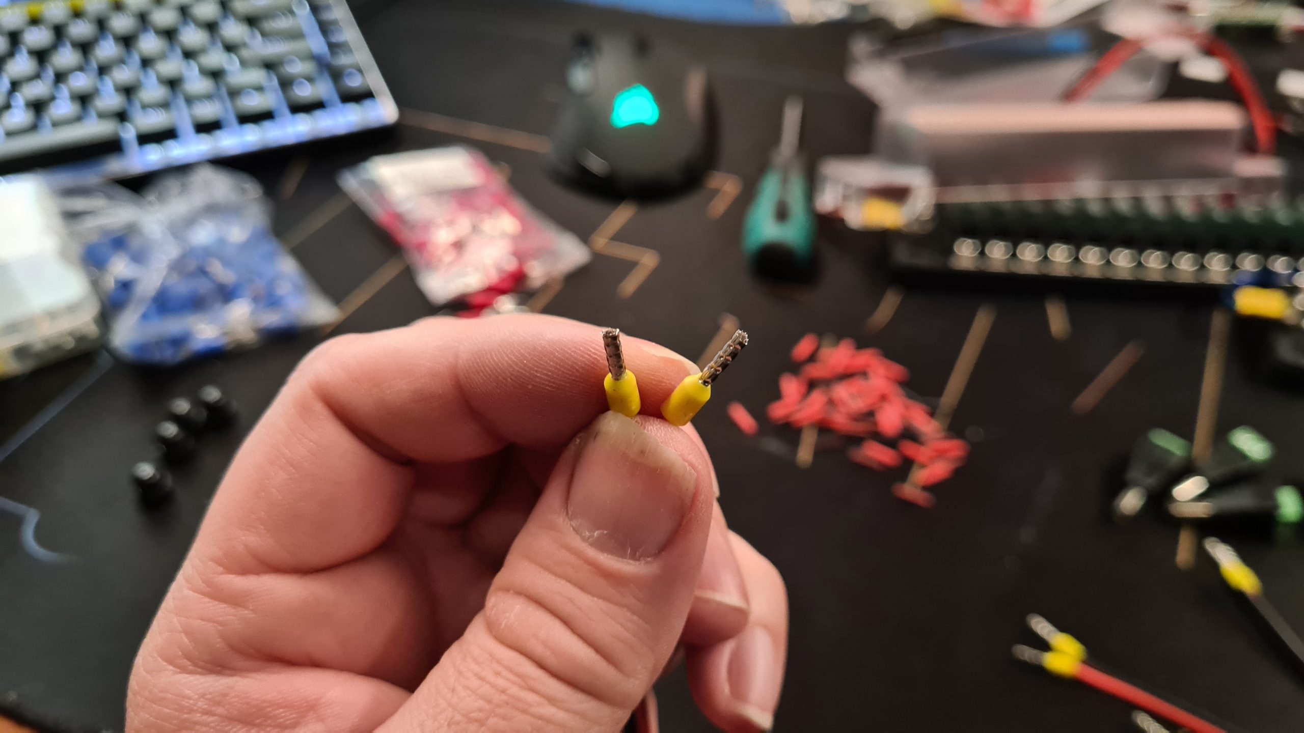 Wire ferrules to make sure you have a good connection with stranded cable
 All done, nice and neat, no more stray wire hairs!
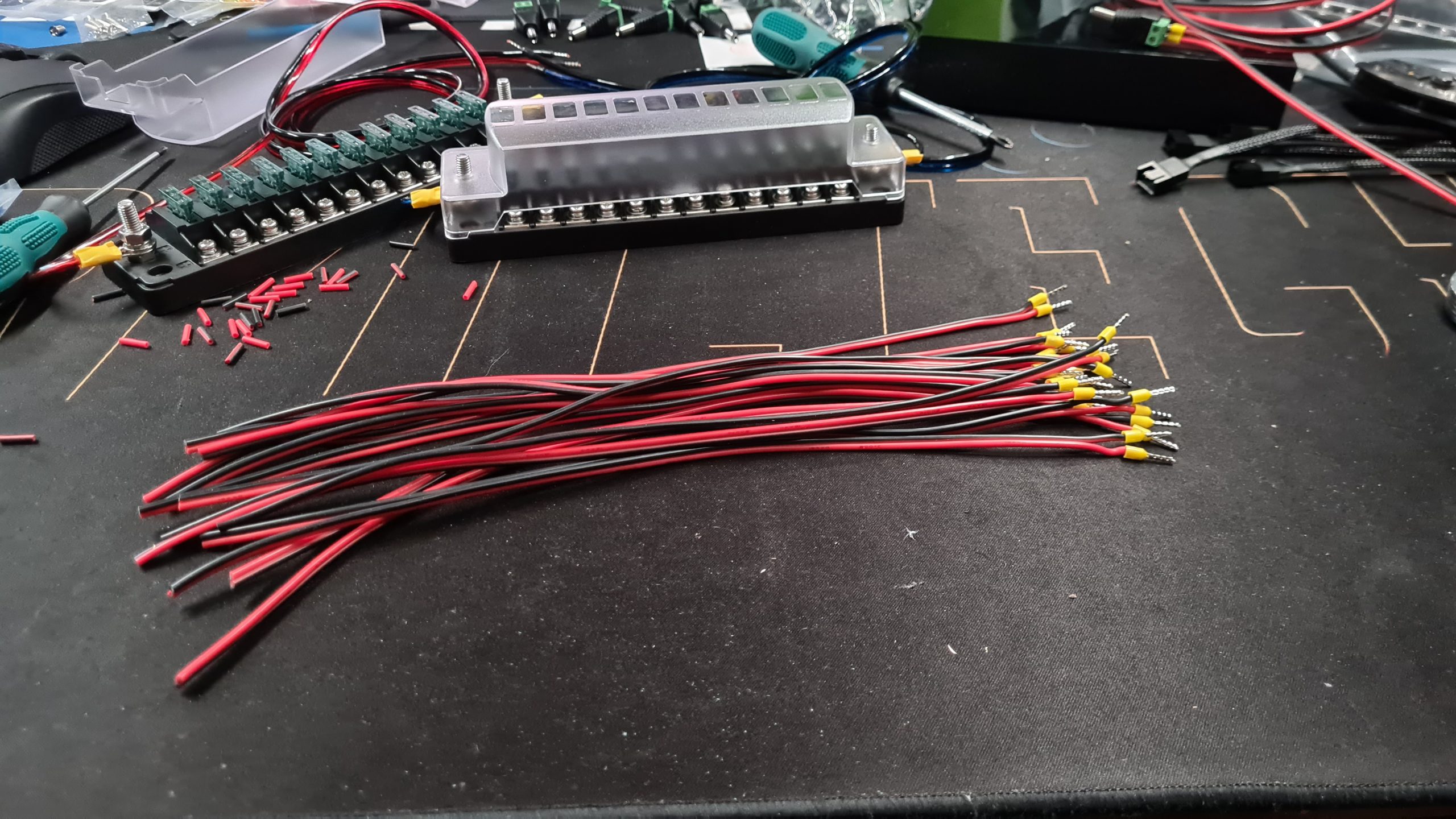
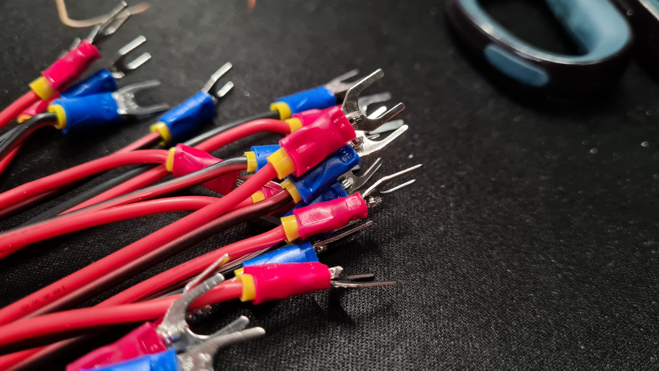
Step 3 – Add crimp connectors
For the AWG15 cables going from the power supply to the fuse/distribution blocks we are going to be connecting the wire to two metal posts. For this a ring terminal connector is advised.
 I used a bigger ring crimp connector then shown but used them all up!
For the AWG18 cables going to your devices I use just ferrules on one side (the side that screws into the 2-wire to barrel plug) and crimp connectors on the other side that screws into the fuse/distribution block.
 These provide an excellent fit for the terminals of both the power supply and then fuse/distribution block!
As you can see in my pictures I used Red and Blue crimp connectors to differentiate Positive/+ and Negative/- but that’s because I had crimp connectors in both those colors and sizes. Using the same color connector is normally fine but if you have/order them in different colors it just makes it easier to keep them separated.
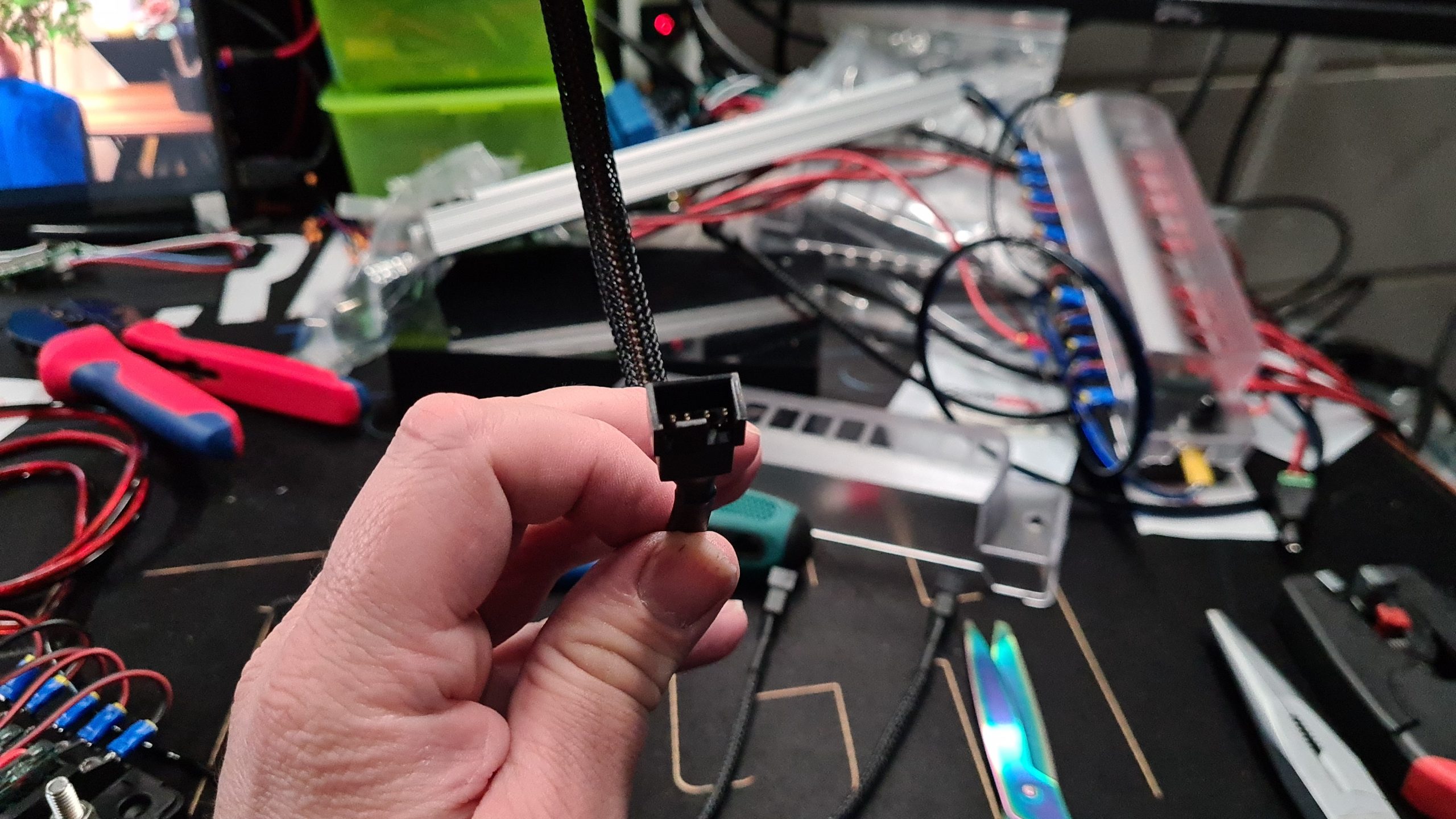
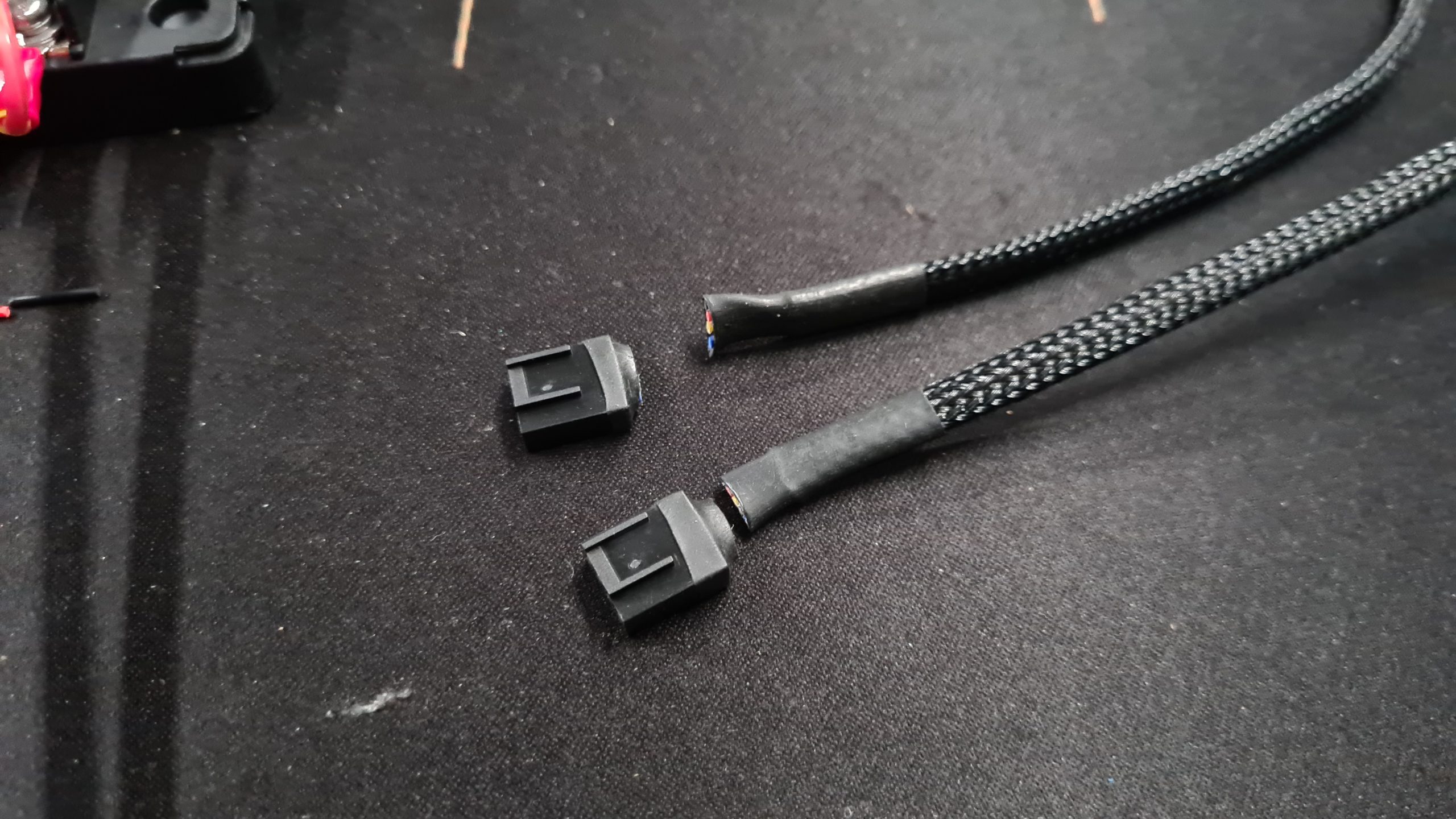
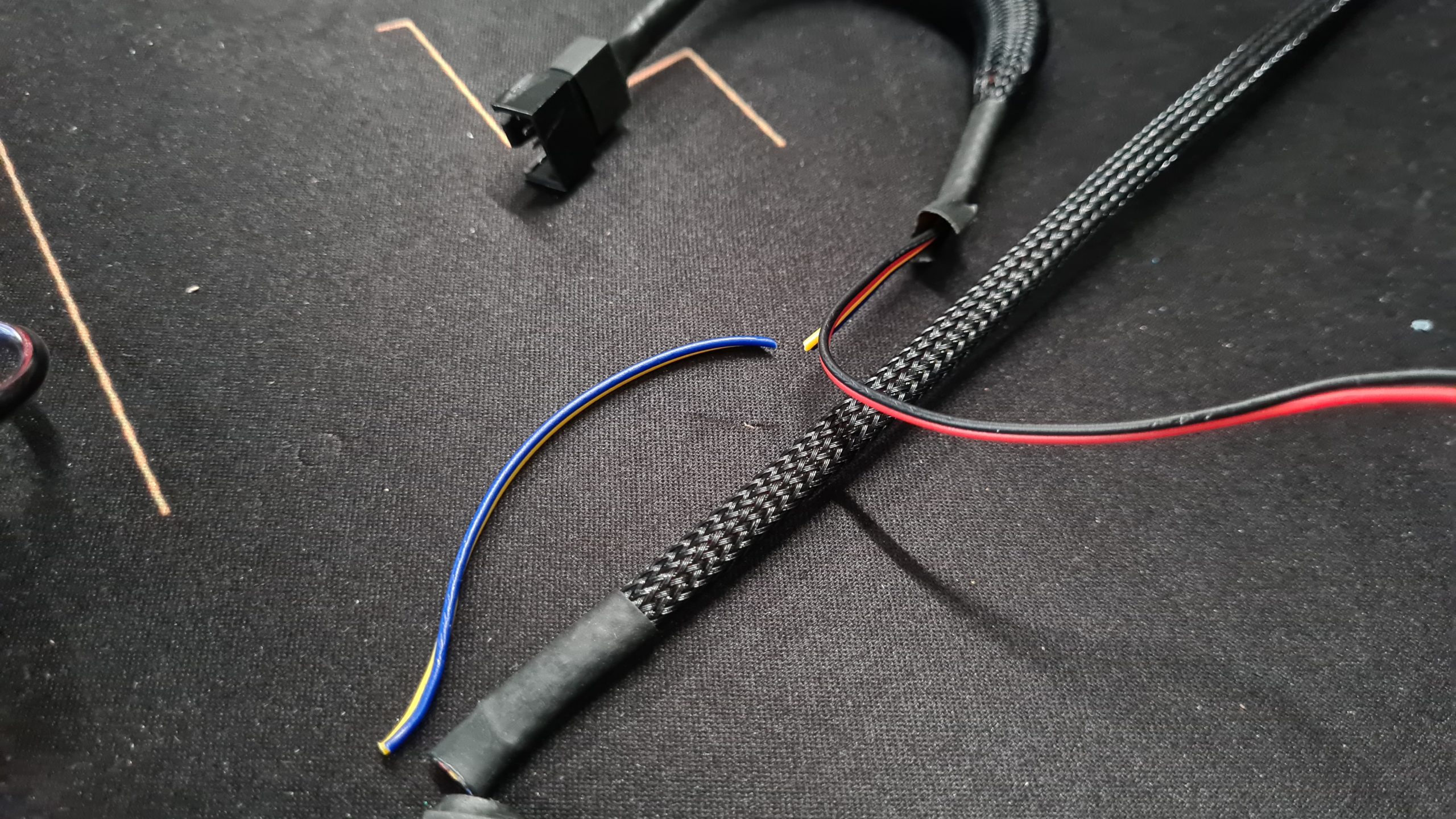
Step 4 – Add 2-wire to barrel plugs
For our devices (Seagate USB3 disks, USB HUB) we need a 5.5mm x 2.5mm barrel plug. Screw these in to the cable ends that only have the wire ferrules. Make sure to pay good attention to the + and – symbol on the plugs and marking on your cable!
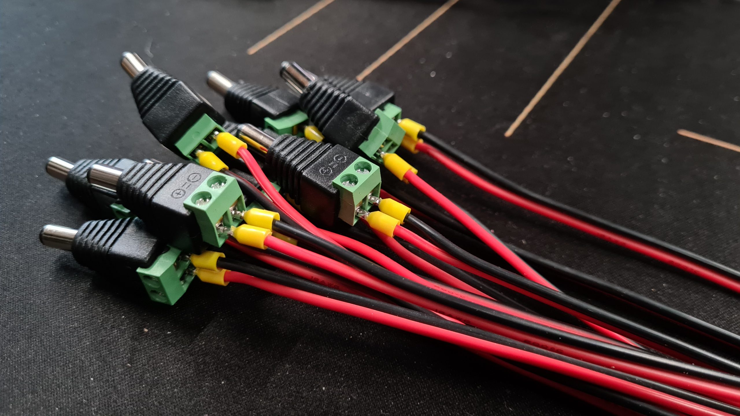 Converted to easily pluggable connections that fit the standard barrel plug holes (5.5 x 2.5mm) of our devices
Tip: Having trouble getting the ferrules into the terminals? Squish them slightly using a pair of (needle nose) pliers! Something about a round plug trying to squeeze into a rectangular hole.
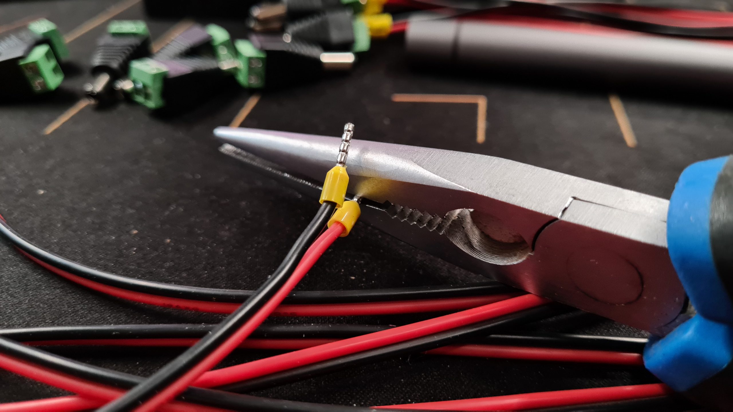 Electricians will probably yell at me but I don’t believe it does much harm and it makes fitting them a lot easier
Start screwing!
Now that we have all the cables prepared it’s time to start screwing!
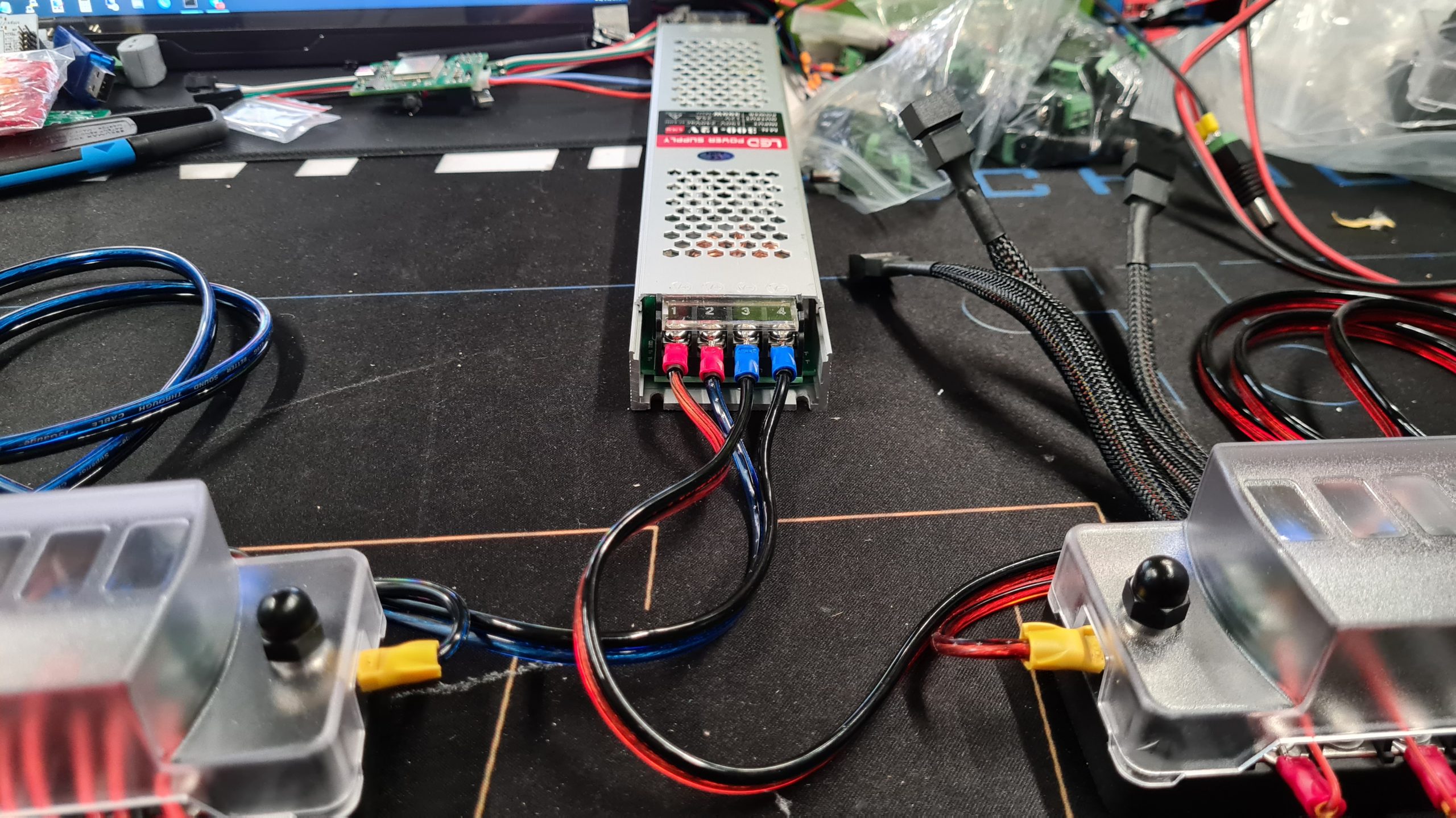
Step 5a – Hook up Fuse/Distribution blocks to PSU
I started out hooking up the fuse/distribution blocks to the power supply with the cables we just prepared. You do this by removing all parts of the 2 posts. Each post will have either a + or – next to it, showing which side it is.
Once you take the nut, ring and washer off, insert your fork or ring terminal cable and put them back in reverse order, so washer, ring and then nut on top. These cables need to go out to the left and right of the blocks to clear the spacing in the top cover.
Get a plier or something like that to torque these down nice and tight!
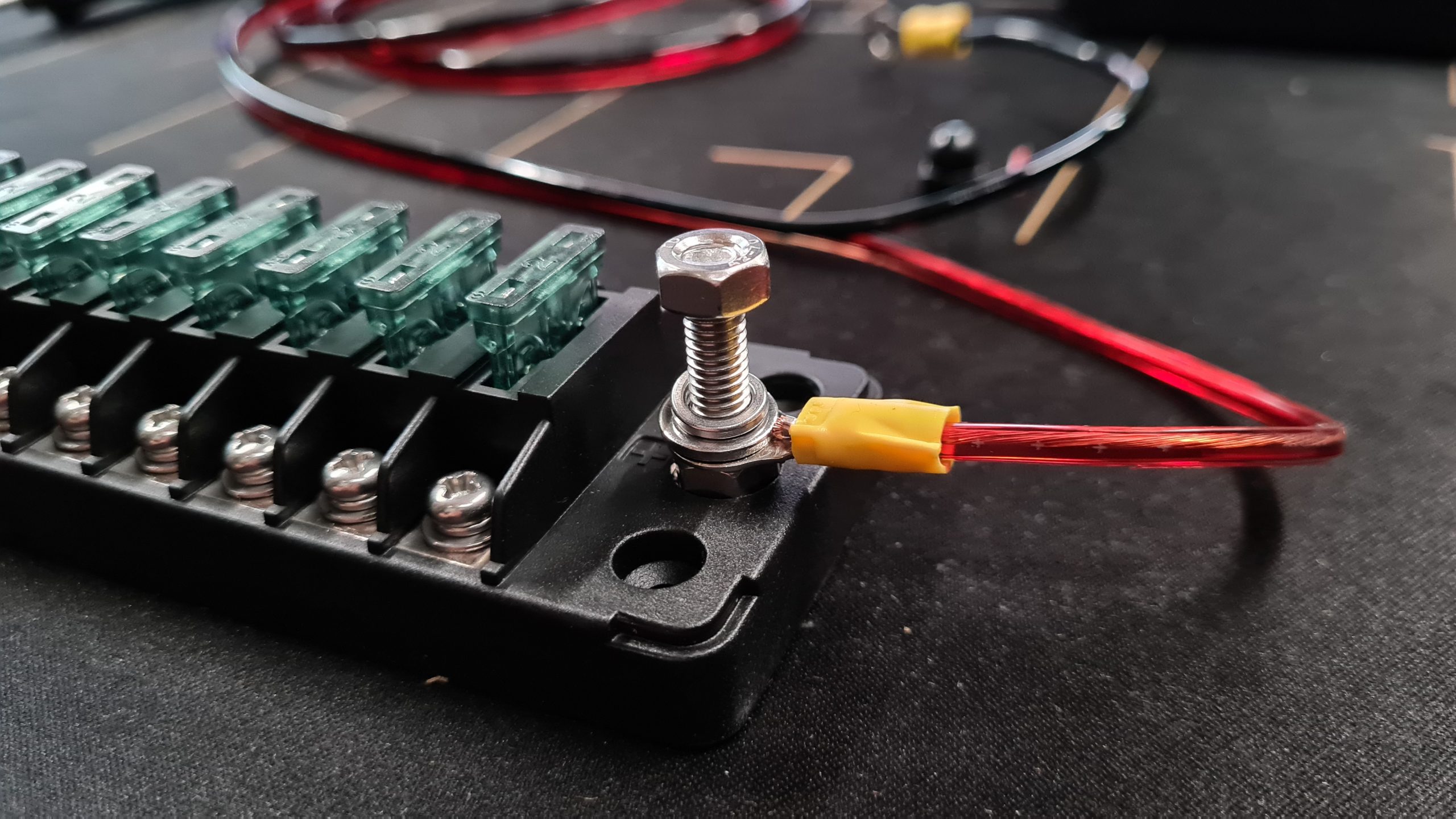 I believe the correct order is ring connector, spacer, locking ring and then bolt
 Tighten it down until it won’t go down any further and you’ll have a very good connection that won’t come loose!
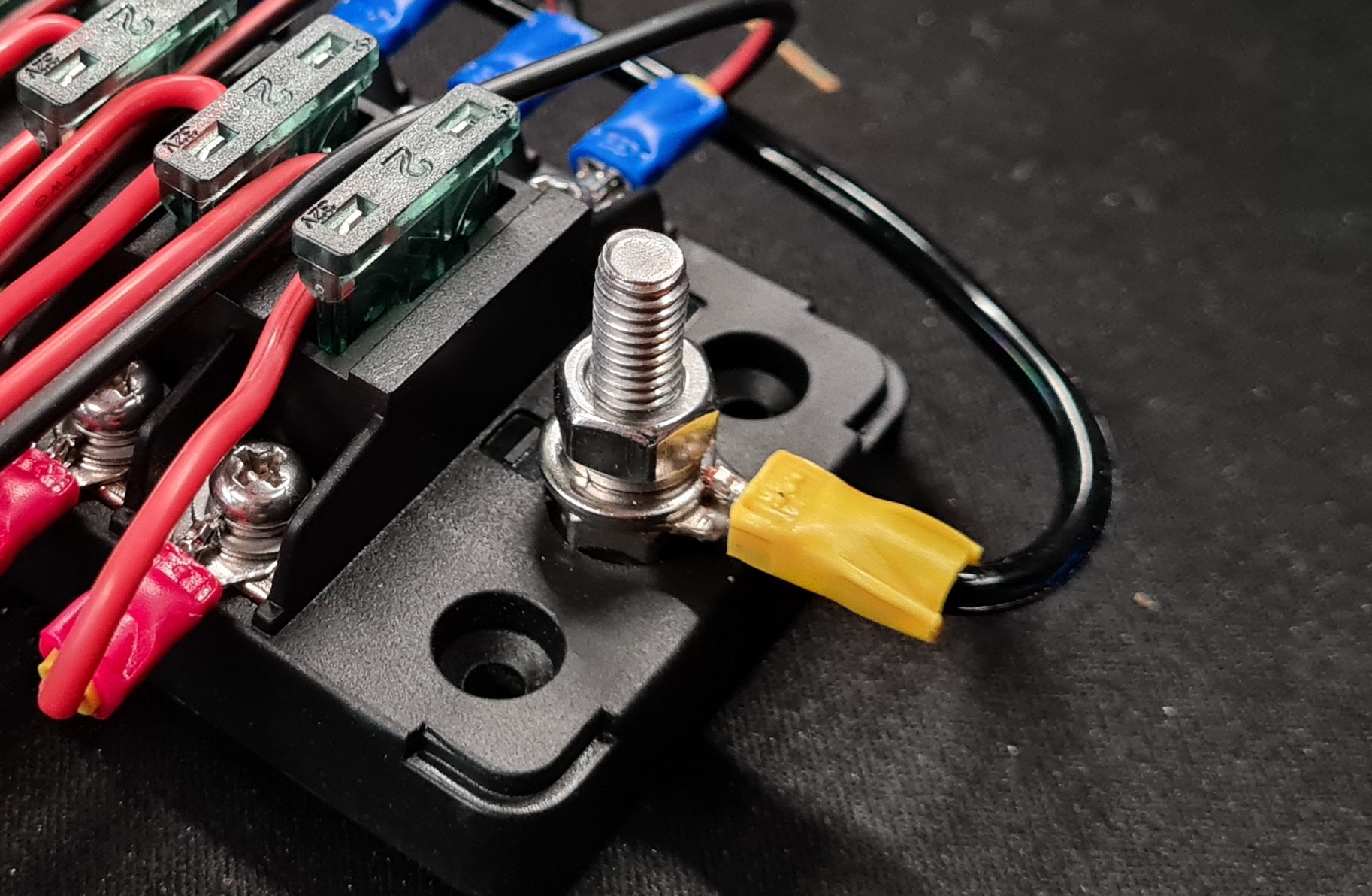
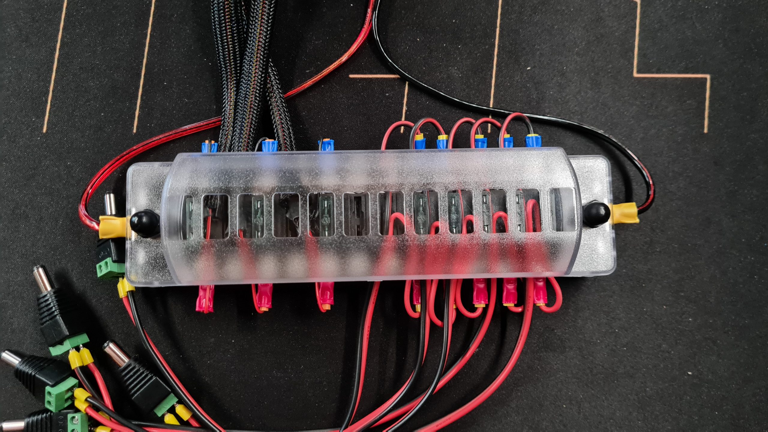
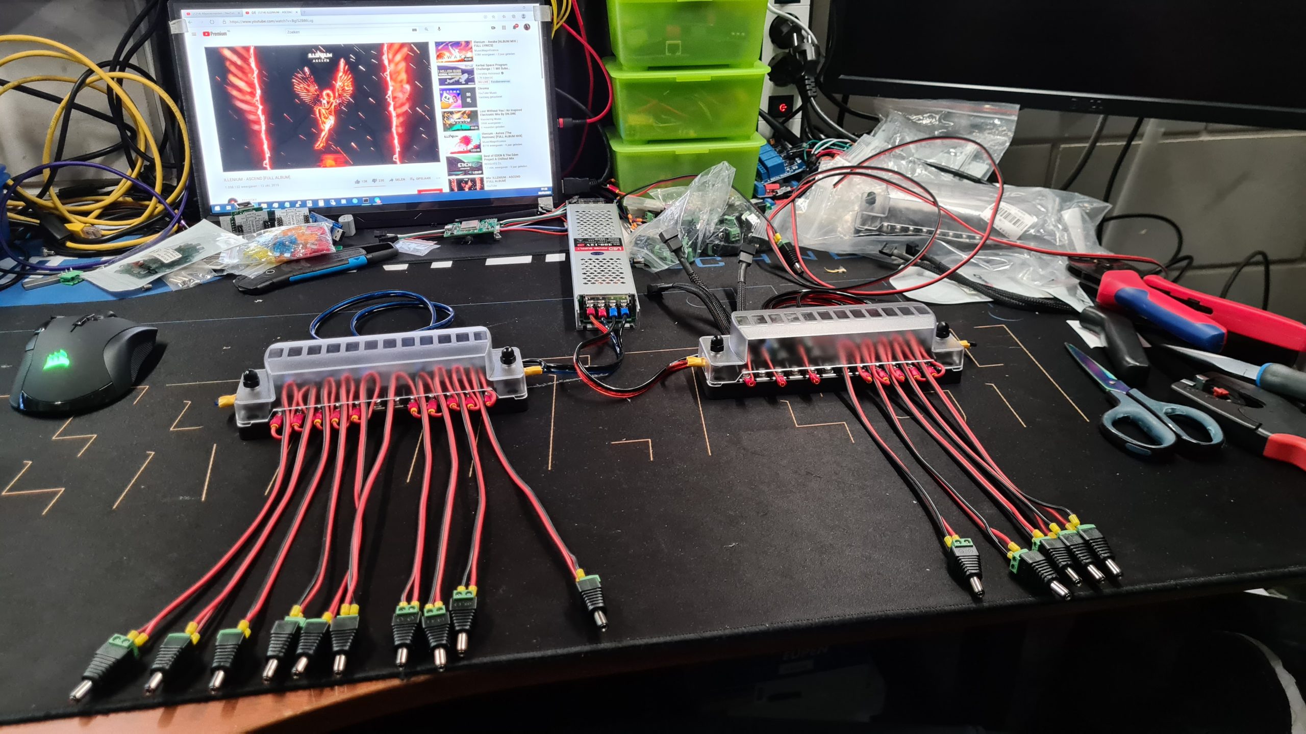
Step 5b – Hook up Device wires to block
Next we screw in all the cables to the fuse block for our devices. In my case I spread them over 2 blocks since I couldn’t fit them on a single 12 port block anyway.
 The fork connectors fit very nicely into the terminals, make sure to put them underneath the ring
During this process, make very sure you are hooking up + and – correctly!
 It looks a bit awkward but it’ll get covered up later on anyway!
 We want this to last a while, strong and secure, fused connections it is!
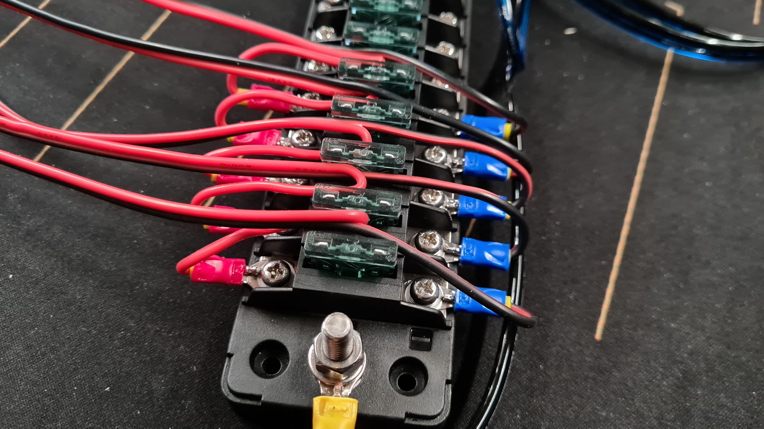
I (ab)used the fuses to nicely tuck away the cables in a way that hides a big part of them when the cover is back on the fuse/distribution block.
 Tuck it away!
 10 connections of 12 used
 Cover still fits on perfectly
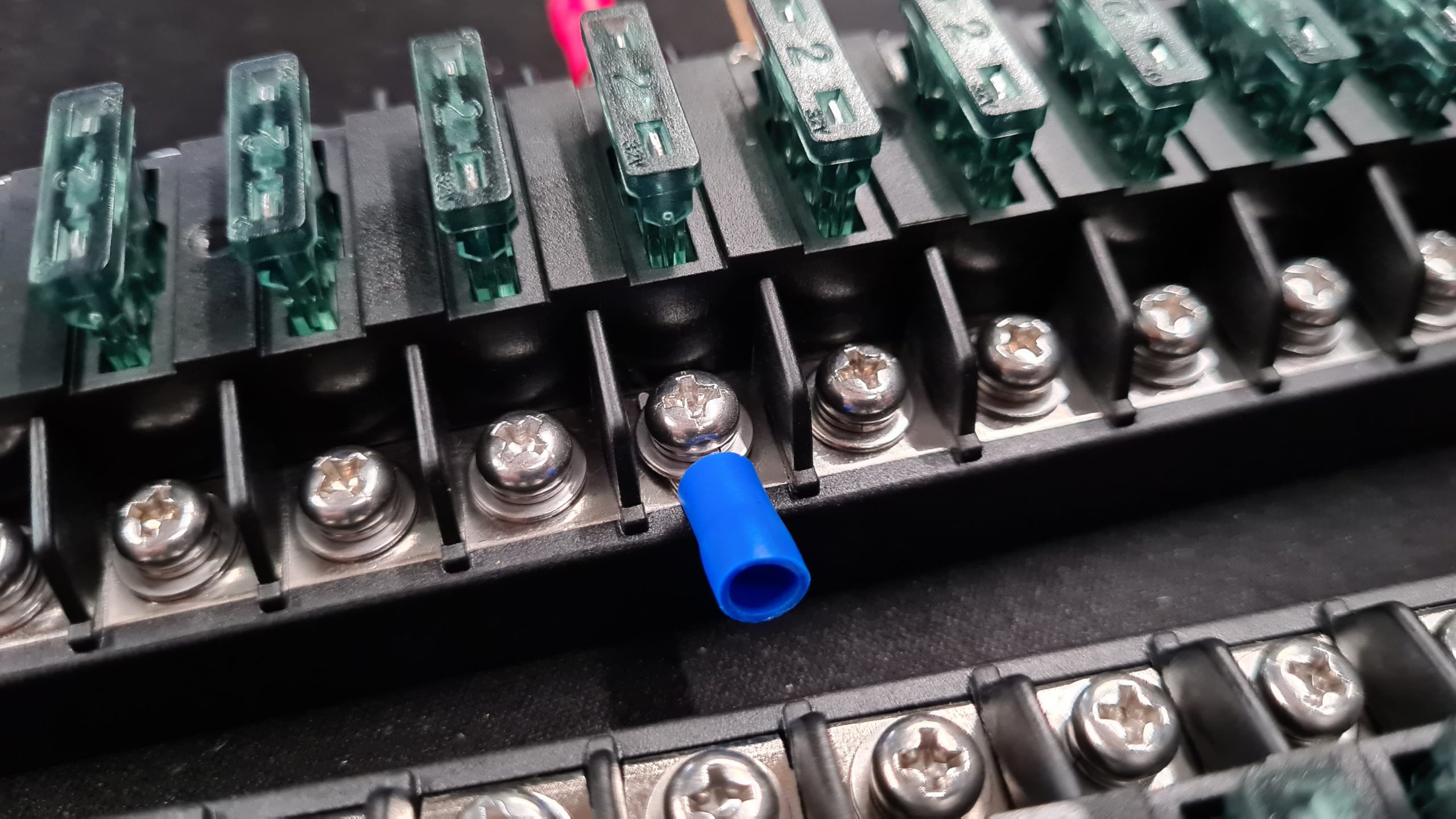
Add fuses
Now that all the wires are connected, let’s add some fuses to the fuse/distribution block if you hadn’t already! If you have the same block I have, each + terminal has an associated spot for a fuse.
Size your fuses for expected load
I recommend using a fuse rated slightly above what the expected average load is going to be for the connected device!
If you expect a 1Amp or lower average load, the best value you can probably use is a 2Amp fuse like I have done for all my connections.
Maybe you are going to have devices which use more power, then you can use a higher value fuse. Most often the included adapter can give you a good hint towards expected power usage in my case they stated 18w or 1.5Amps at 12v out.
I like doing my own measurements though with the linked PR-10C power meter to make sure.
A fuse won’t pop instantly
A fuse is a thermal device and won’t instantly pop. Or rather a 2Amp fuse can take 3Amps for like 20 to 30 seconds probably before popping. However give it 10Amps and it’ll pop within a second.
In my case the disks ask ~15w during their startup phase but then settling down to ~5w each, a 1Amp fuse would have been perfect, but I didn’t have any and a 2Amp is close enough. Certainly well below what the cable can handle as a maximum (thus if a short would happen, the fuse will always pop before the cable melts/could cause a fire).
Total max power of a block
Also keep a total max power in mind. Although we’re using ~50cm of AWG15 to feed a single fuse/distribution block, and that can carry a decent amount of current, there is a limit of course. I’d feel ok loading a single fuse/distribution block up to 25Amps (the 300w my PSU is capable of) but I wouldn’t go much above that.
If that was sustained load, I’d also beef up the AWG15 wires to maybe AWG12, just to make sure. Length also plays a role, a shorter cable will be able to handle more Amps then a same thickness longer cable.
USB Hub power
Since I have a USB HUB that takes 12v in, I also need to create and connect a cable like we’ve made for the disks but a bit longer for it. Although the USB HUB comes with a 90w adapter, we’re not going to be using much power at all since all our devices are self powered so a 2Amp fuse will do just fine for that.
Powering some fans
To create some airflow we’re also going to be using some PC fans. I generally have a bunch of these lying around so I grabbed some 140mm types and prepared some wires for them.
To make life easy, I bought a 5 pack of fan extension wires and just snipped off one end and then connect the wires to the fuse/terminal block.
 Extension wires
 This side we keep
 Snip this side off
 Open up the heat-shrink a little bit and pull out the wires
 Snip off the yellow and blue, only need Red (+) and Black (-)
After this, connect some wire ferrules and fork connectors to the end of the fan wires and hook them up to the fuse/block! Again the lowest value fuse (2Amps in my case) will do.
 I put the fan wires in so that they come out the other side
Wire up Power Supply
Last step is to wire up the power supply. Again we’re using some wire ferrules and fork connectors to make sure we have a good and tight connection.
AC Side
Make sure nothing is plugged in while working on the AC or DC power supply wires!
AC power can be a bit scary but in this use case we really don’t need to do much. I generally take a existing “computer power cord”, snip off the end we don’t need, strip those wires, add some ferrules and fork plugs and screw it in.
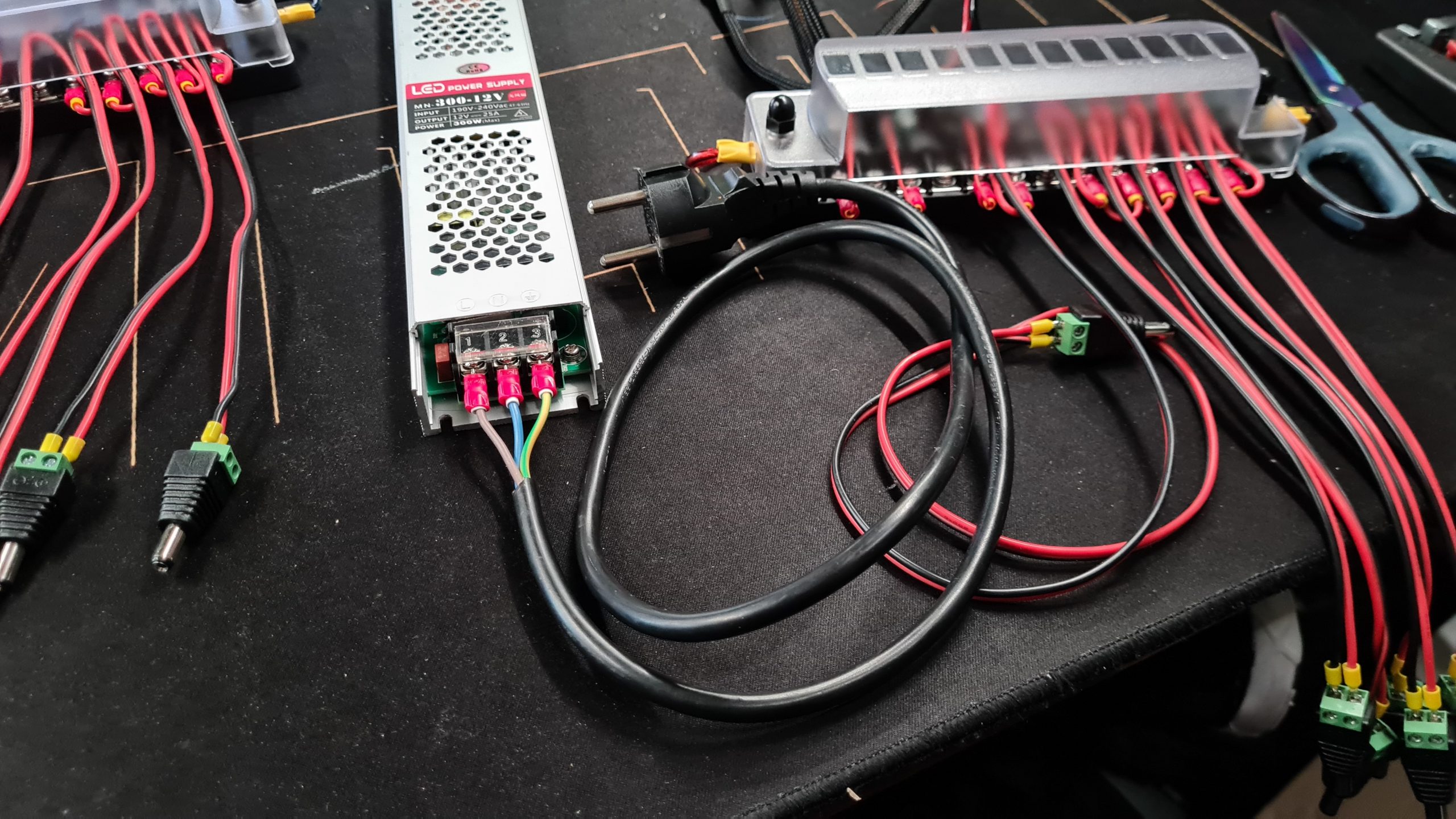
In Europe use these wire colors for AC:
- Live – Brown
- Neutral – Blue
- Earth – Green/Yellow
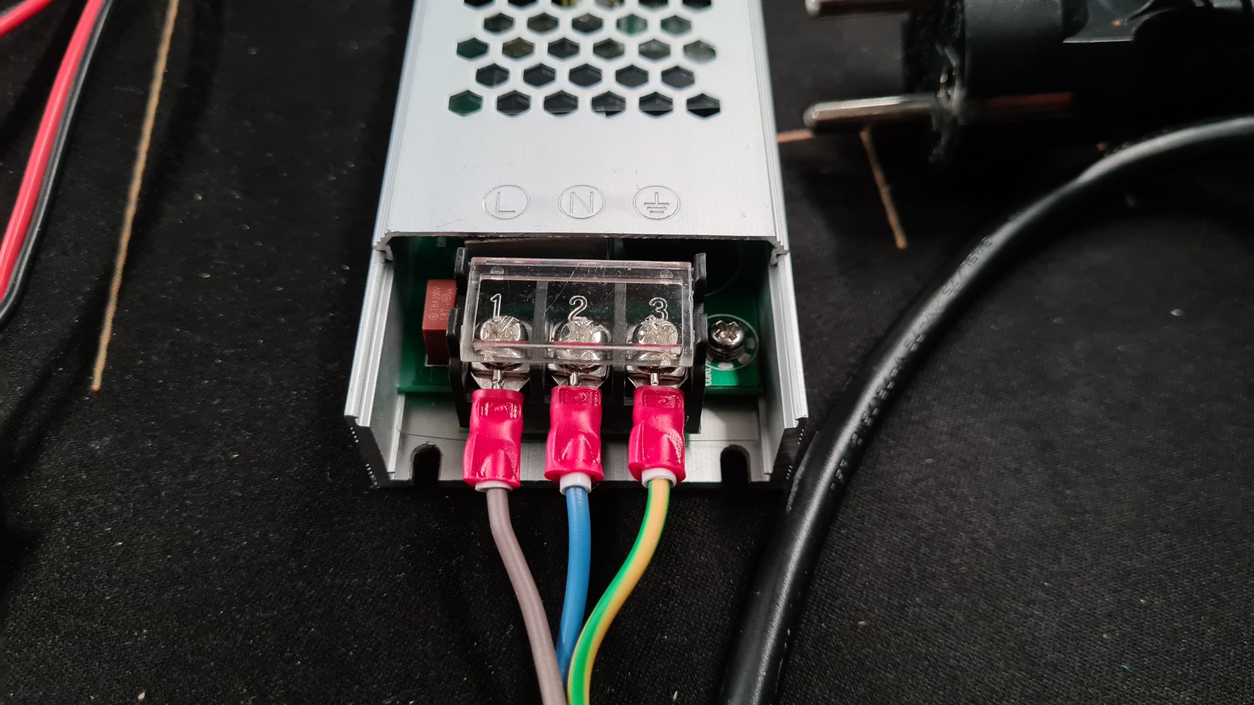 AC side wired in
DC Side
Then we need to wire up the DC side of the power supply, since we have 2 sets of terminals available I wired in each fuse/distribution block we are using to individual terminals.
 Using using fork connectors to make a good and secure connection
 Nicely wired up!
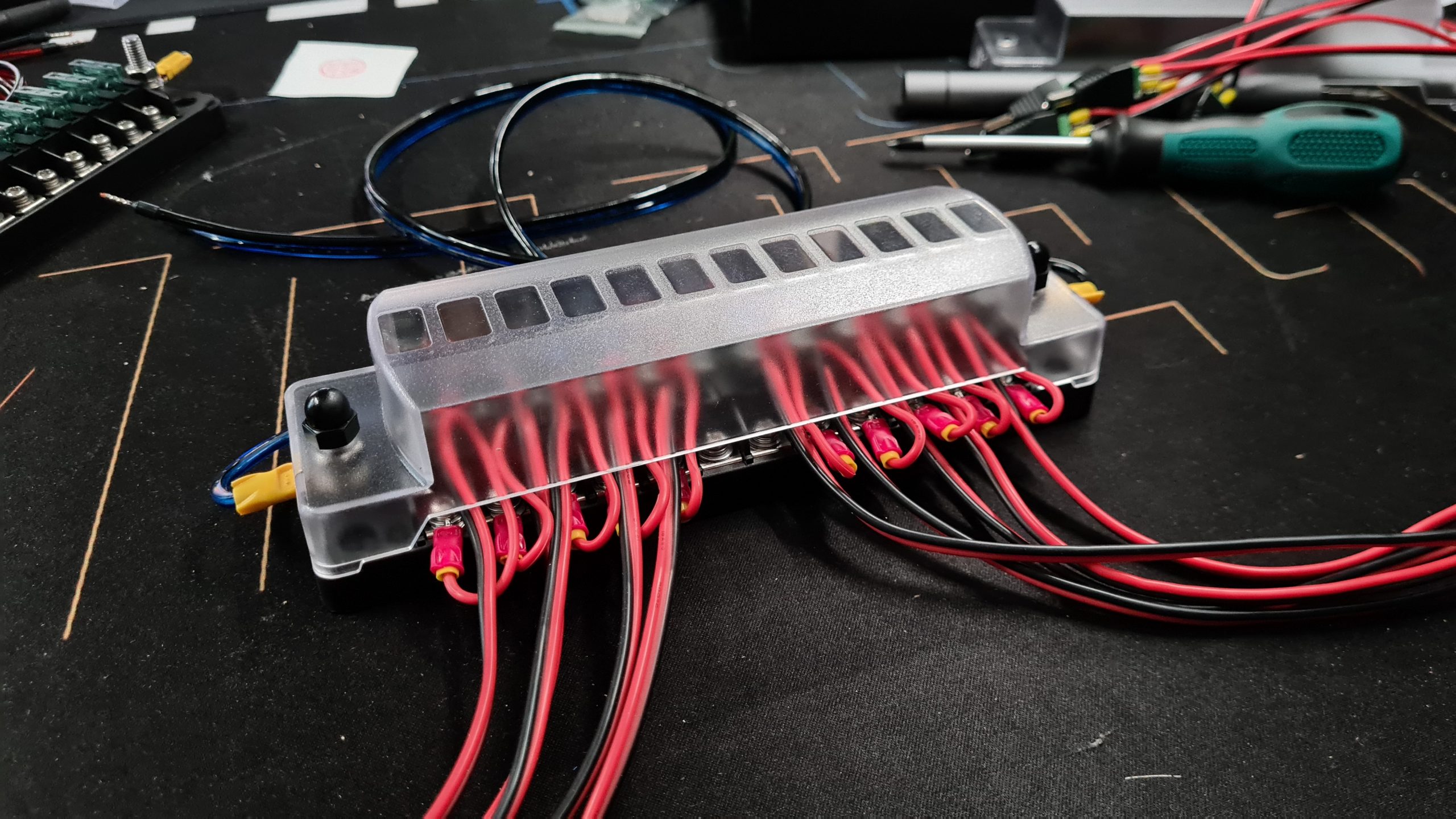
That should be it, let’s test it!
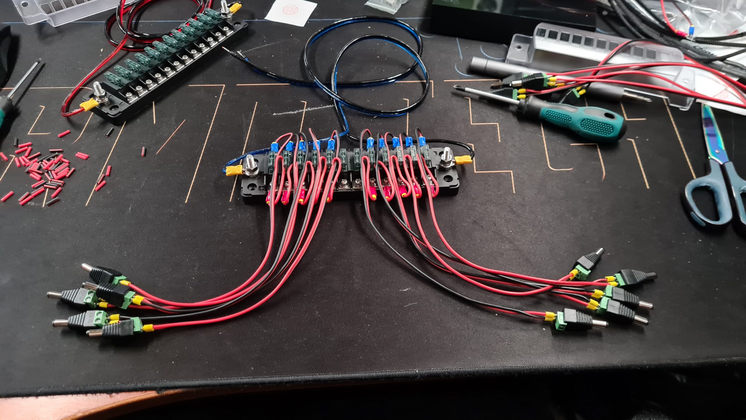
Ok, that should be it and now you should have something like this:
 All wires prepared, everything looking good!
Let’s do a quick test to see if it’s all working as expected:
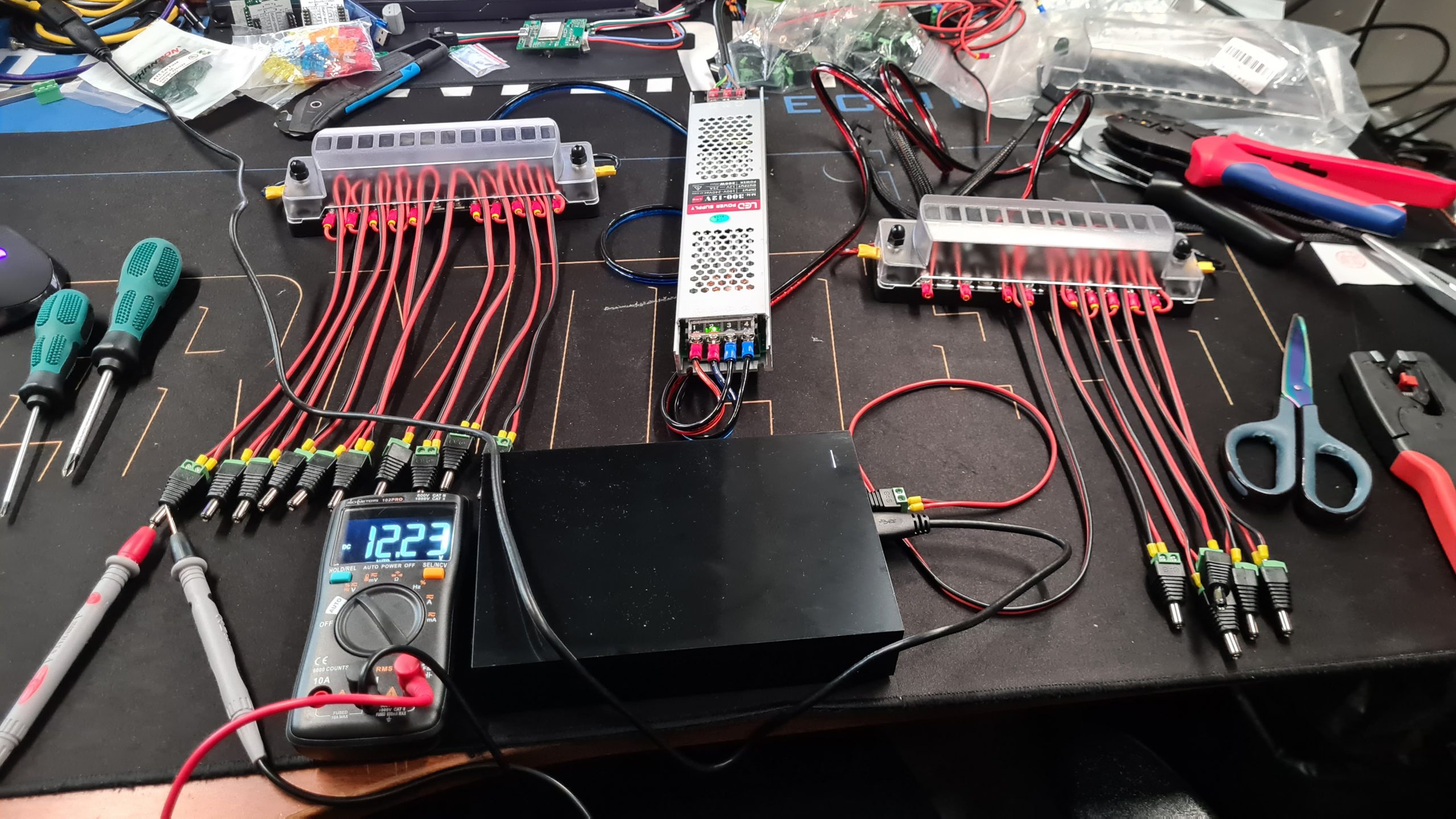 Measuring 12.23v with a disk connected and spun up, all good!
(These Seagate disks will not spin up without an active USB connection!)
Time to install it all!
Ok with everything tested and all looking good, let’s replace the previous setup and all those adapters!
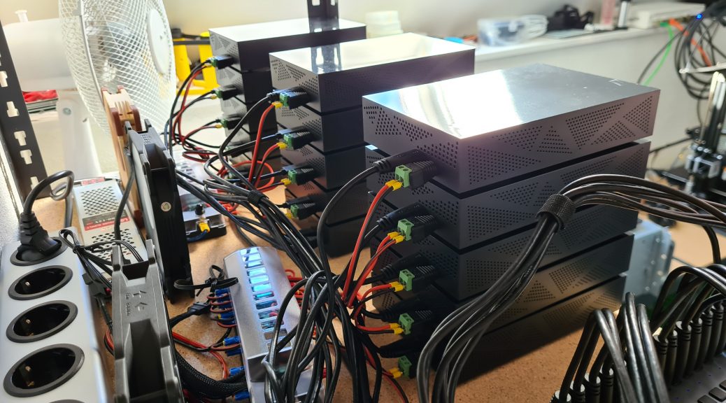
Situation with all the adapters
Here I only have 9 of the 15 disks running as as you can see it’s already quite busy with a bunch of adapters, bunched up wires and the likes.
 It tried to make it look nice, but after a while, it just becomes a mess
Replacing it
I measured the new wires to make sure they won’t be too long or too short for my intended situation. I decided to just keep the large power bar in the back and then have the 300w power supply. In front of those the 2 fuse/distribution blocks.
Let’s start wiring it up!
 Disks looking good, waiting for more!
I also added the 3 fans in the back of which two are near to the power supply providing it a bit of airflow too since by itself it’s only passively cooled.
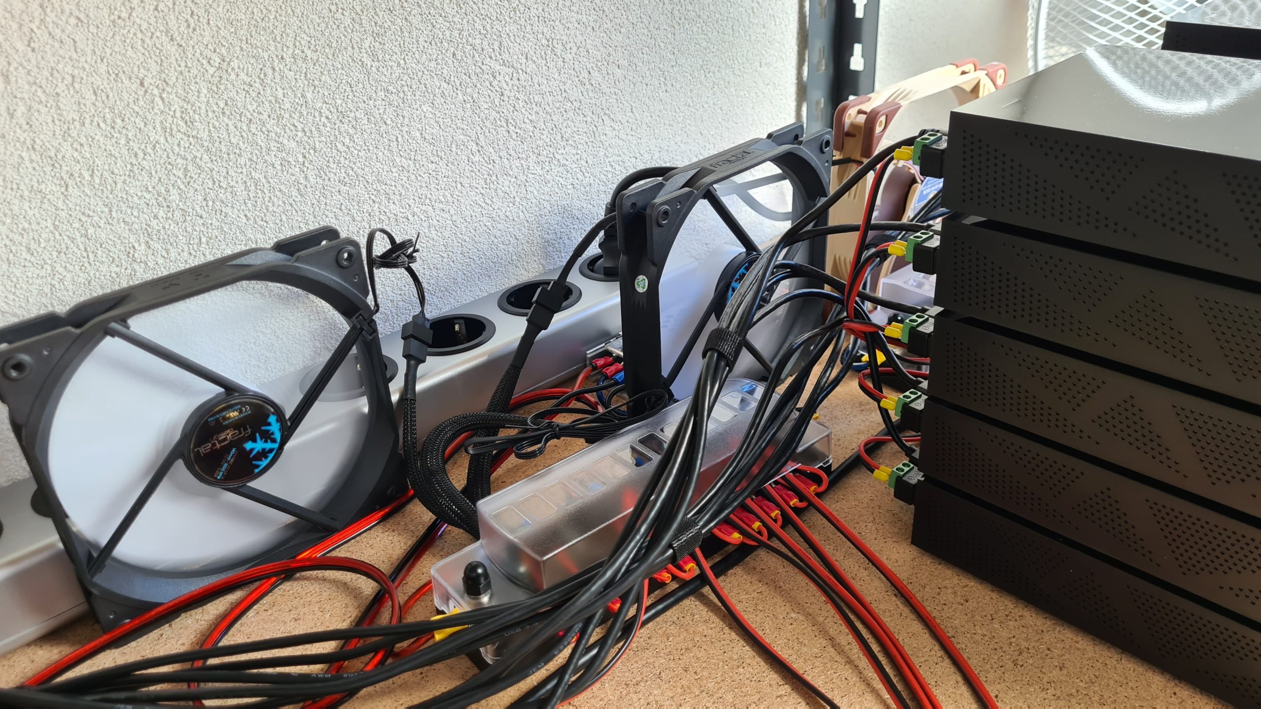 A bit of airflow can go a long way!
 Used some Velcro to try and tidy up some of the cables
(Don’t tie them together too tightly, it could affect the data signals)
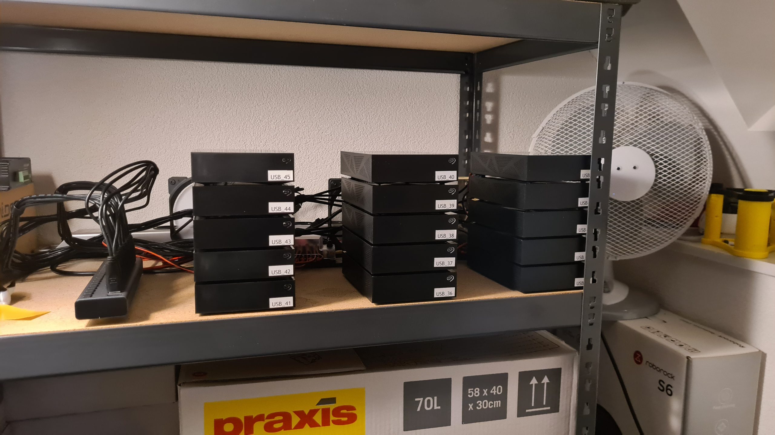
Final installation
After those shots I installed all drives and these have been running without issue for the last few days!
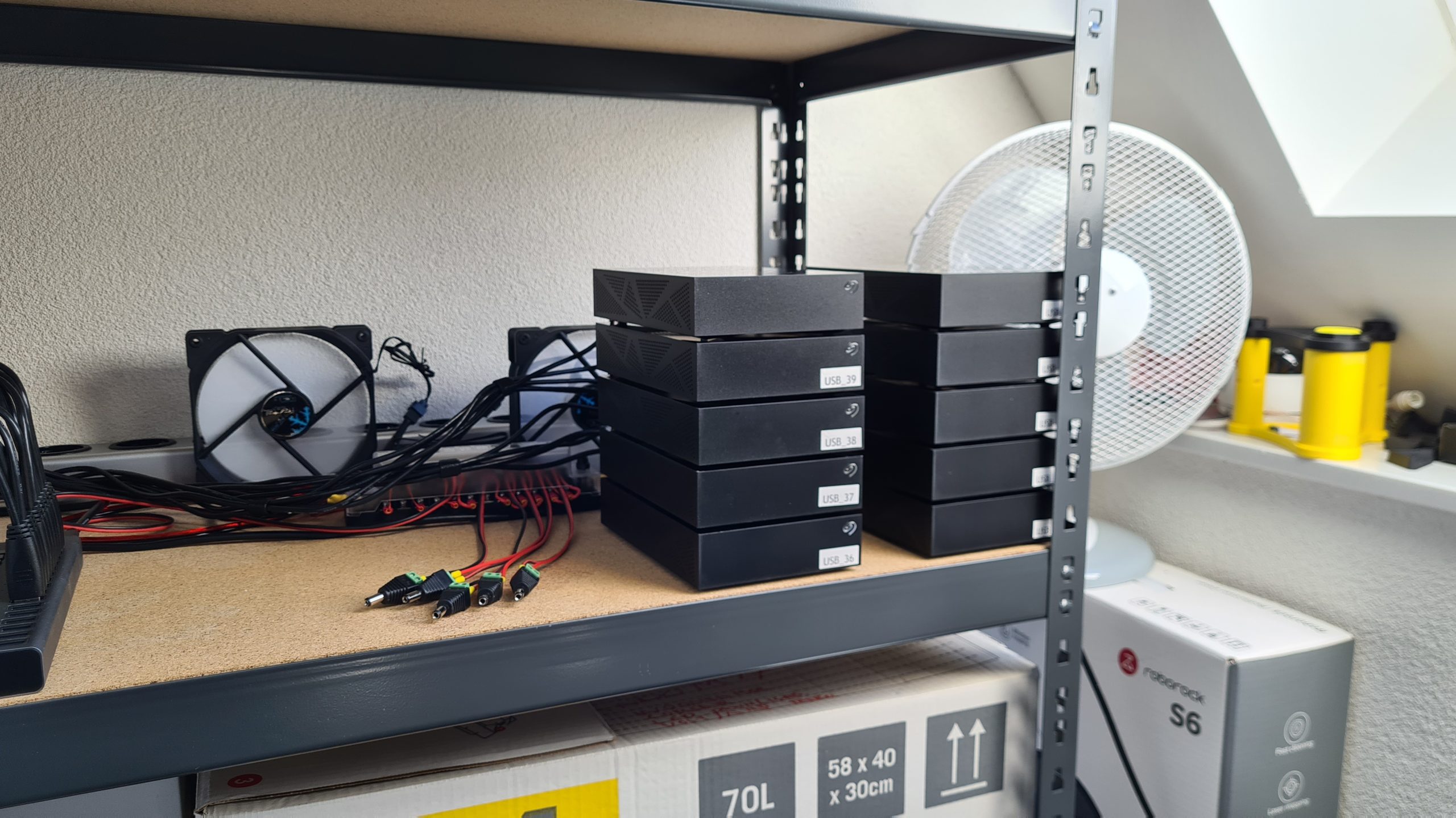
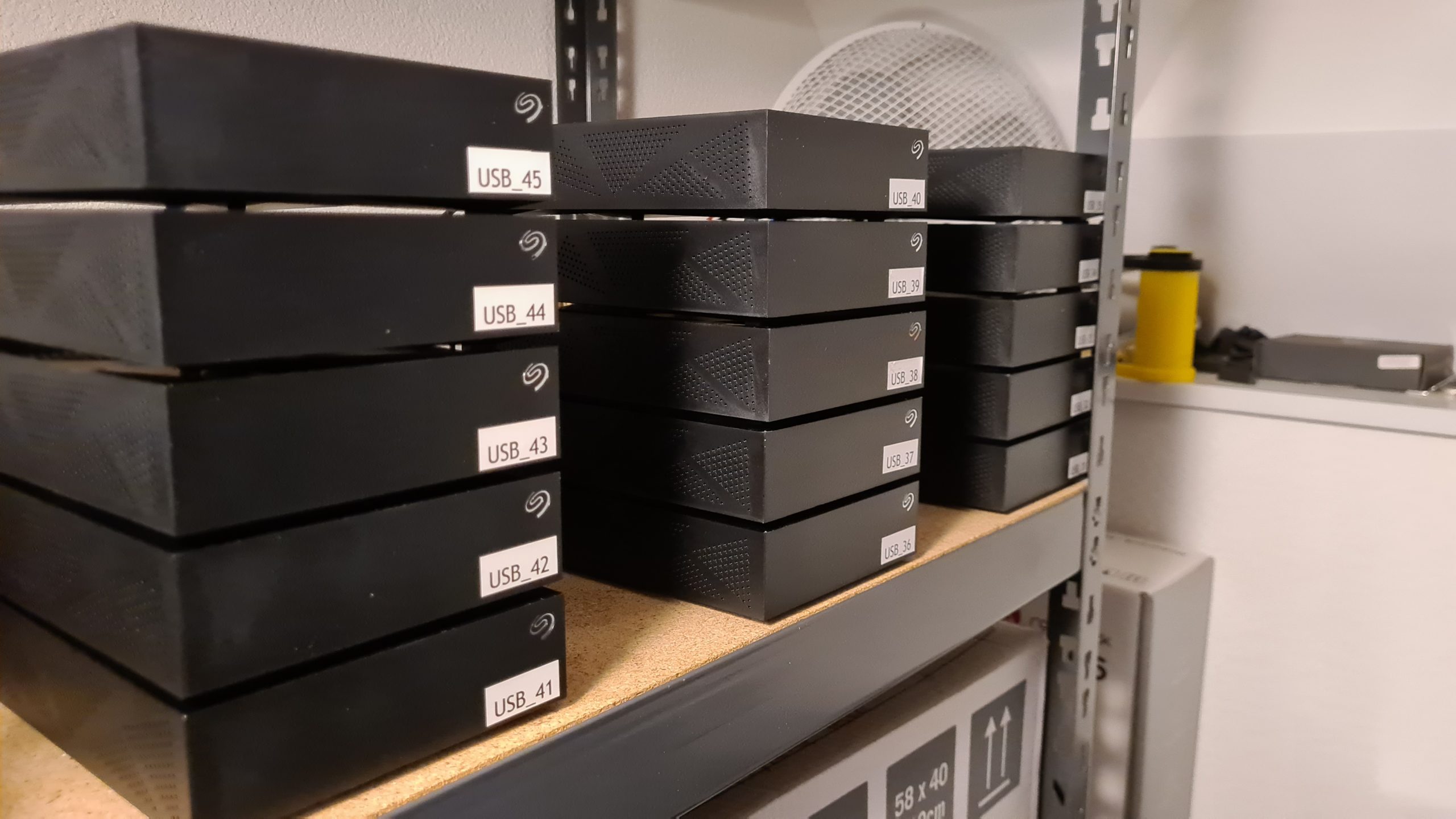 15 disks, nicely purring along
 Not sure why the front plastic of the first 5 is different from the others
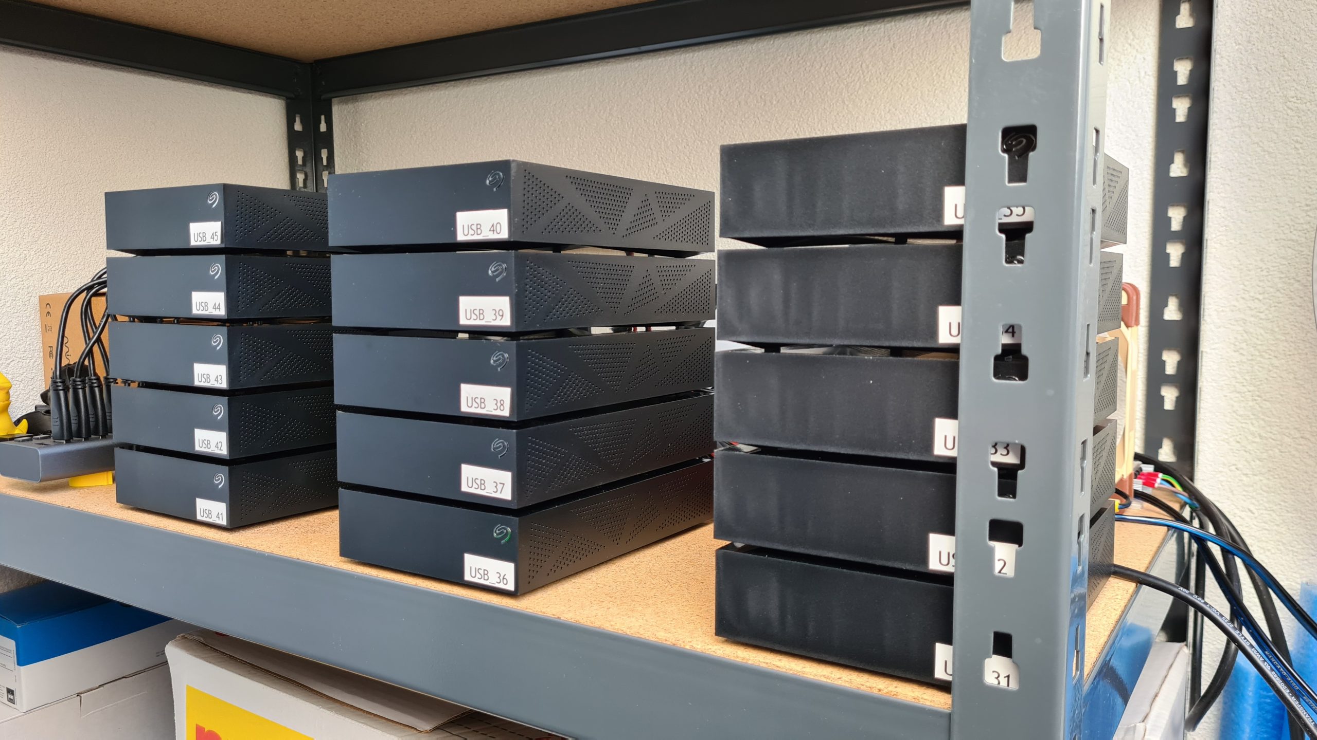
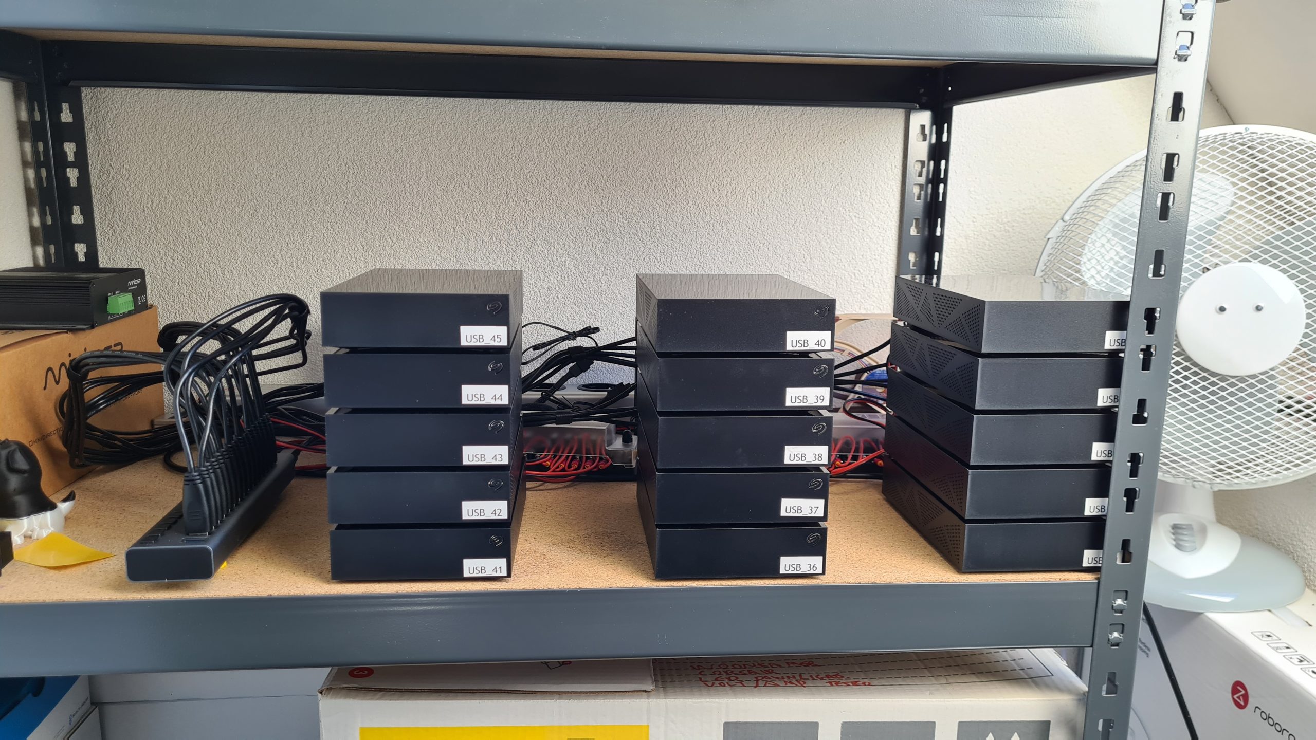 Can’t hide all wires perfectly
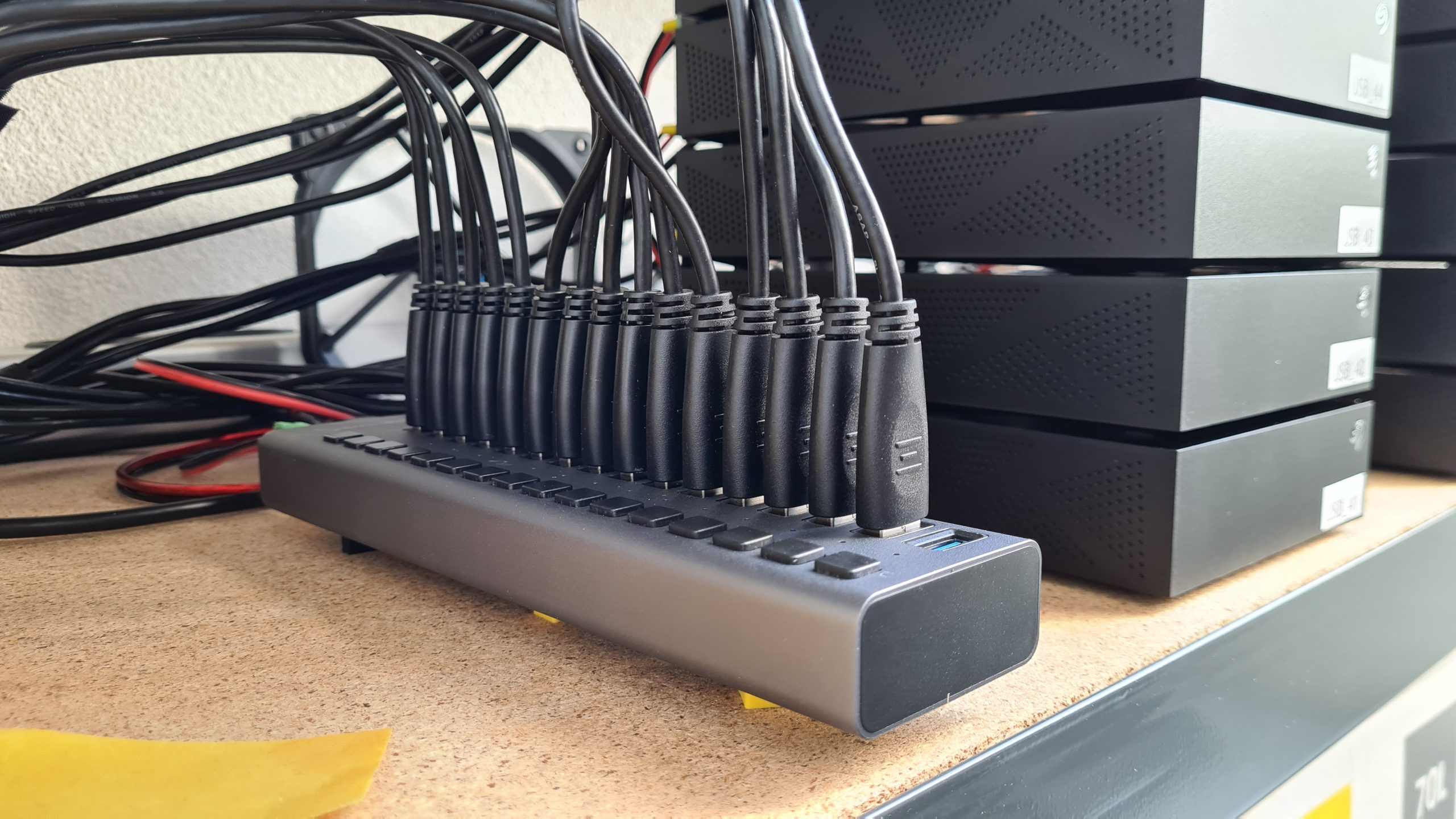 Look at those plugs!
Backside of all the wiring!
Of course there is still the same amount of wires, they are just now much better in regards to length and well, they still need to go somewhere.
 Looking nice and tidy and easy to follow what is what!
–update
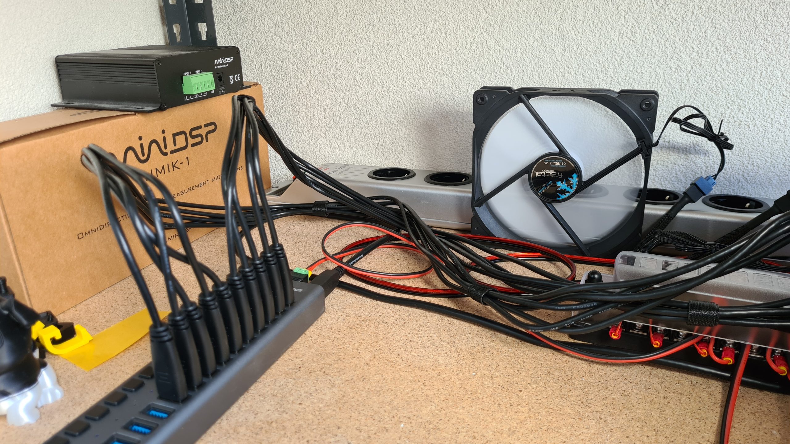
I’ve rewired the USB3 wires slightly. I run ZFS on the external drives (each drive is it’s own pool) and I noticed 2 data read/CRC errors in about a weeks time. I’m not 100% sure if I had those before or not, but because of that I decided to move the cables to the front, routing them away from the power connections and other wires as much as possible, since then I haven’t seen a single error, so I’d advise this as good practive.
 Still bundled per 5 cables
 View from the back
This might require a bit of more room then initially designed for but if you can incorporate it into your design that not all of the data and power cables are running for long lengths right next to each other, that’s always a good thing!
End conclusions
All is working well and I am very happy with the setup and how it’s improved from the situation with all the adapters.
The disks still run a bit hot (50c on average) since they are still in the enclosures but the airflow does seem to help carry the heat away. To improve it further I’d have to shuck them out of the case and I’d like to prevent that if possible, so we’ll see how it goes over time in that regard.
For now it’s been running for a few days already with 0 issues. “Cold” starting is also no problem at all and the power supply handles it without issue.
Amazing guide! Thank you for the insights, I am bookmarking your blog
I am very happy to see this are you going to sell same
I am ready to but
Thanks
Hi,
thank you for the information and sharing this project.
I had something like this in mind for a while, cause i really hate all the small power supplies, that accumulated over time (currently 6 external drives).
With Chia growing, and people keeping more and more data, what do you think about making these for people? I have no technical knowledge pertaining to this and since there’s no off the shelf solution for this, it would definitely be worth the money to get one of these made.
Count me in! I would also be very happy to buy this!
I need something like that for normal SATA power because ATX PSUs allow only 4 HDDs per cable and most PSUs have only 5-6 peripheral connectors.
I wonder if you can somehow use PCIe cables and some PCB to split 12v to 5V and breakout board for as many HDDs as possible.
Can you say anything about the powerconsumption after the changes? I would be interested in doing this but mostly for power saving. Is this one powersupply more efficient than all the small adapters? I was unable to finde good information on the specific efficiency of every part.
Thanks for this guide!
yeah really nice project. impressively innovative. I’m going to have bookmark this page.
I am very happy if you sell one power as same
I have been looking to buy something like this – Since you made this – have you seen something like it that can be purchased? I may make one – can you tell us what it cost approximately?