ESP8266 WiFi LED dimmer Part 8 of X: Version 2 of the PCB design
Quindor
With the help of kind internet folks I was able to get a fritzing part for the new voltage converter I wanted to use to try and make a smaller board. A few weeks ago I sent my new ‘panalized’ design to dirtypcb’s and I got them back last week. They are awesome! Read on to order the boards yourself!
I have released version 2.6 of the QuinLED board which comes with improvements! Check it out over here!
The need for a smaller board
The first design of the QLED dimmer was my amateur attempt to create a PCB board with the components I had at the time. And while it works just fine, some things in the design I really wasn’t very happy with.
So, I set out to design a new v2 board and improve on all those things and also try to make it as small as possible.
v2 managed to do this! It is very small and keeps all the features of the v1 board except for the resistor spots. I really see no practical use for them and all my boards have been functioning just fine, for months, without them.
The reason why I wanted to make the board smaller is because I want to use them inside of electrical sockets inside my house. I’m not yet completely sure of how I’m going to accomplish this (Mostly I am in need for a small power supply) but having the board fit is the first part at least.
The new board
The new board measures 50mm x 23mm in total. So basically it’s v1 cut in half. This opened up an interesting option. DirtyPCB allows you to use a panalized design for your PCB’s. What this means is that a router can cut your PCB in shapes, at no extra costs.
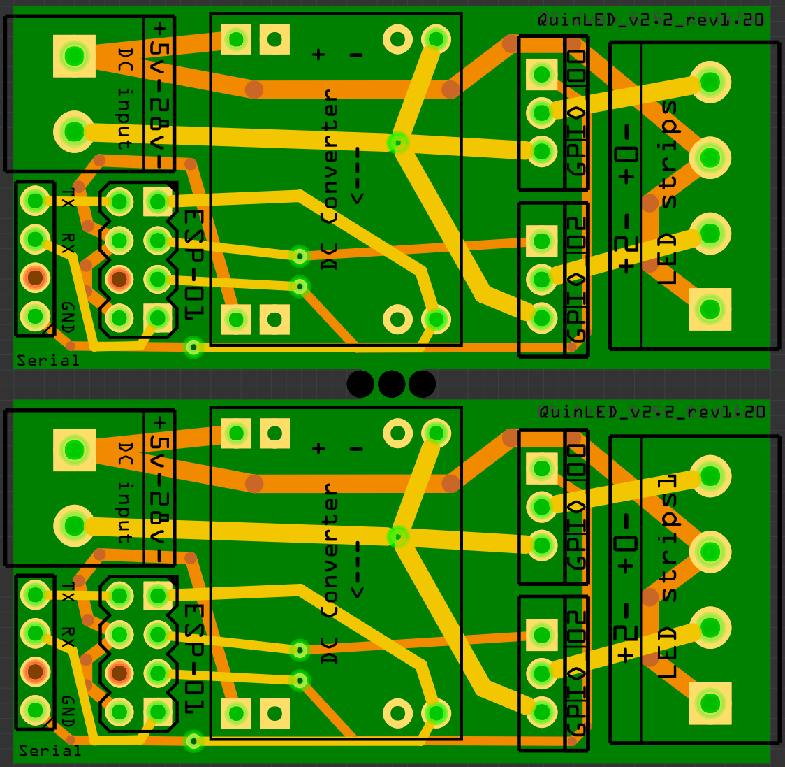
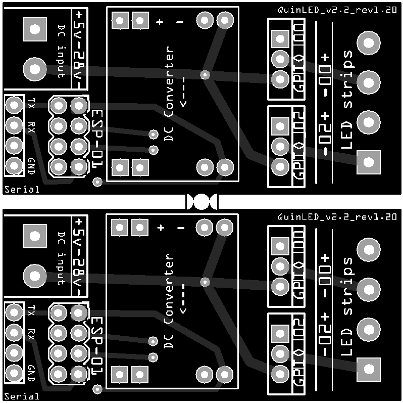
That led me to design it as following:
Panalized design
Basically you create a custom SVG file which becomes your board shape in the end. This means that the 10 to 12 boards you get from dirtyPCB’s for 14$, now become 20 tot 24 boards! v1 was already cheap, but v2 is half (in PCB costs). Incredible value!
Since I wanted to be able to break the boards apart easily I made the computer create some drill holes in the middle, leaving only a little bit of PCB connected together. This works perfectly.
I also took some time to improve upon the first board such as lining up the + and – connections on both sides of the board. Including TX, RX and a GND pin. And routing all paths in a “smoother” fashion, (supposedly) improving conductivity.
For me, I’m not really using the RX and TX because I will be using the ESP-01 inside of a socket, raising it above the 2 pin power connector and hovering it above the DC-DC power converter. I had a discussion on a forum about this being wise or not, but I decided to try it anyway. After having run the boards for a week or 2 now, I see no issues with doing this.
The result
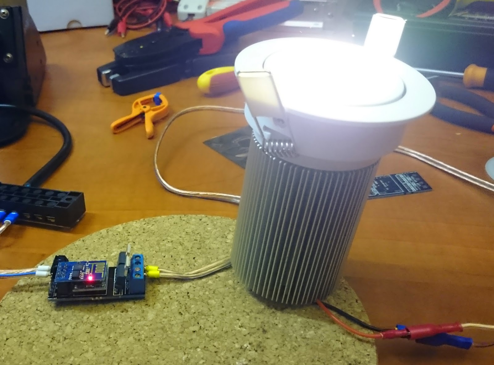
I’m VERY happy with the end result. Up to date I’ve soldered together 4 boards and they have all worked perfectly. I tried each board with 12v LED strips attached and with a 38.5v COB LED light attached for several hours. Perfect results for every board.
38.5v is above the specifications for the voltage converter but since we are only pulling a very small amount of current through it I believe it will not form a problem. I have tested one for days and the voltage converter does not even become warm or show any other signs of trouble.
The boards as they come in, same size as the previous board, just now 1 is 2!
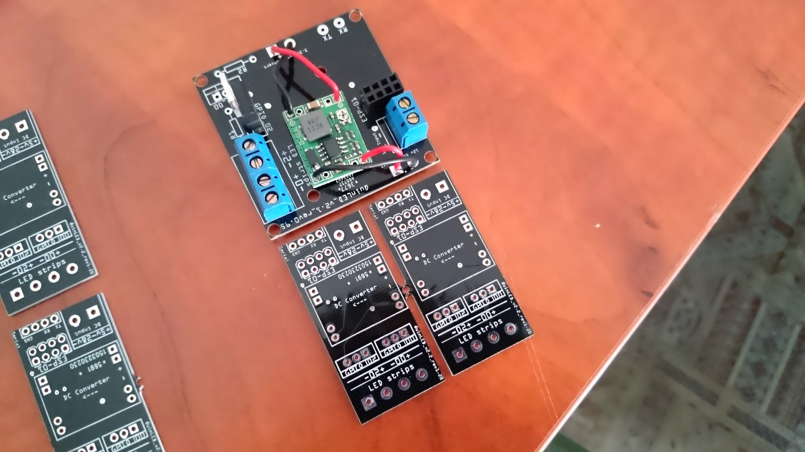
Broken apart
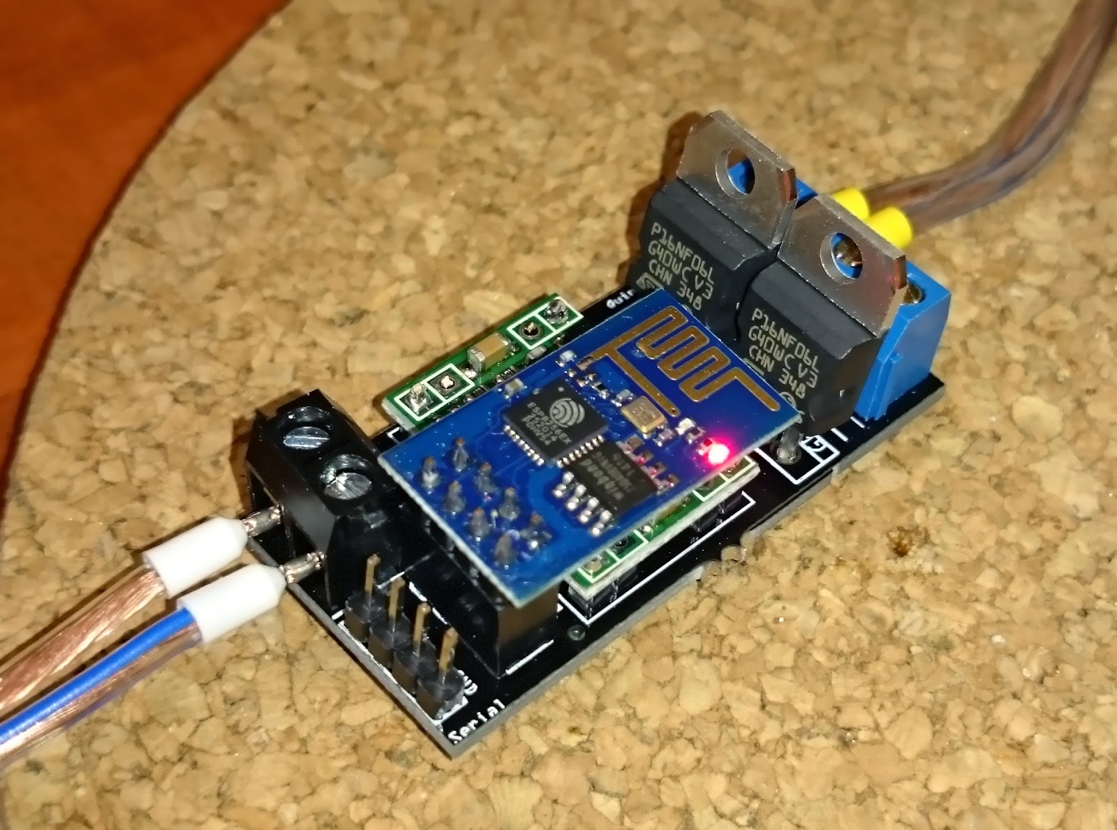
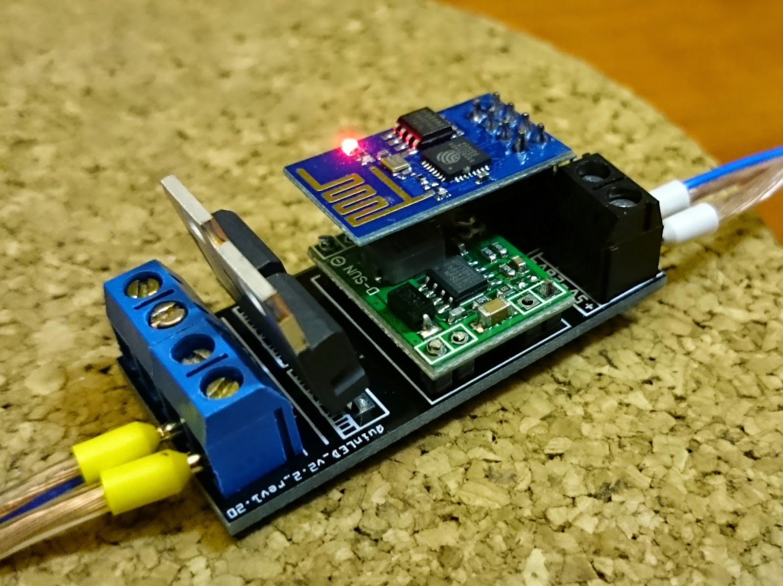
Soldered together
Mosfets at an angle for easy soldering 😉
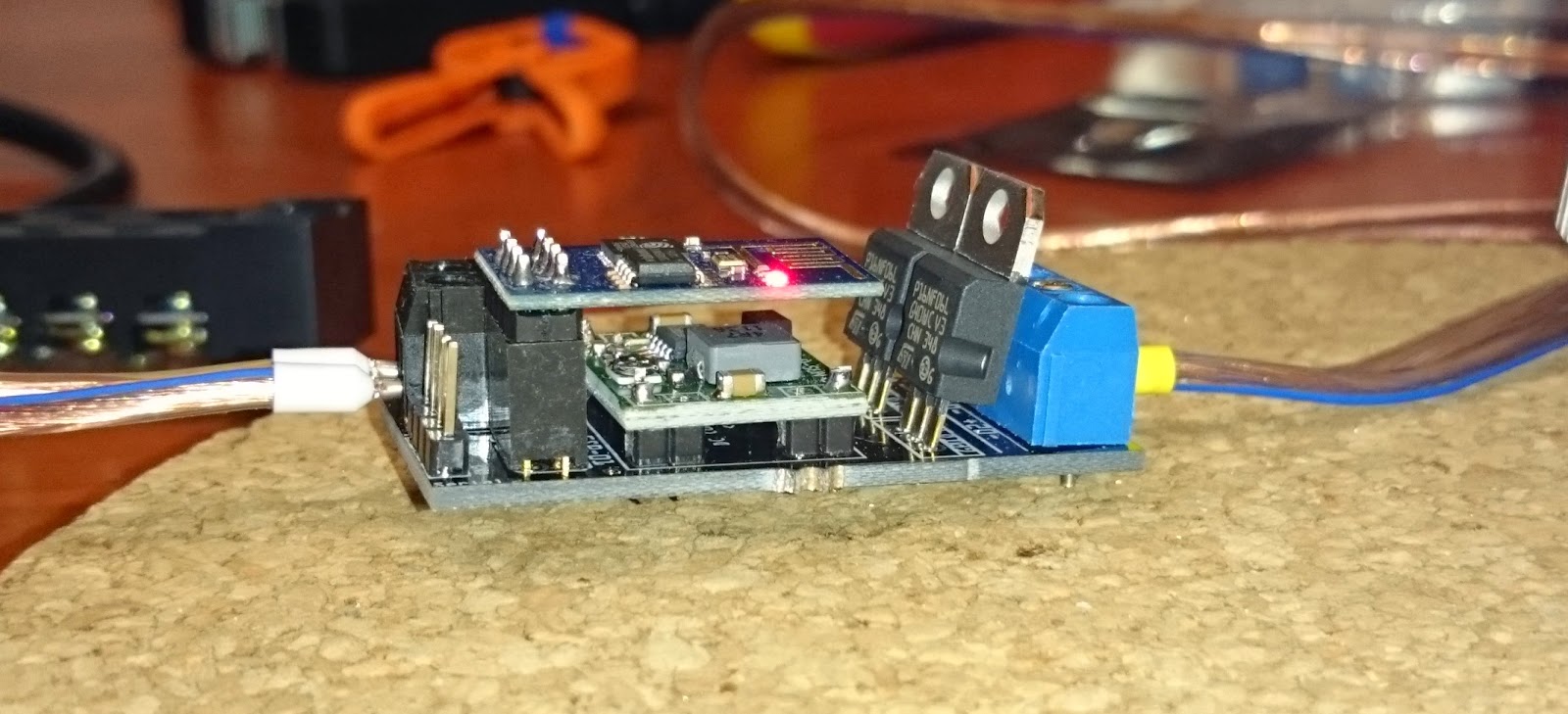
Although close together there is more then plenty of clearance between the DC-DC converter and the ESP-01
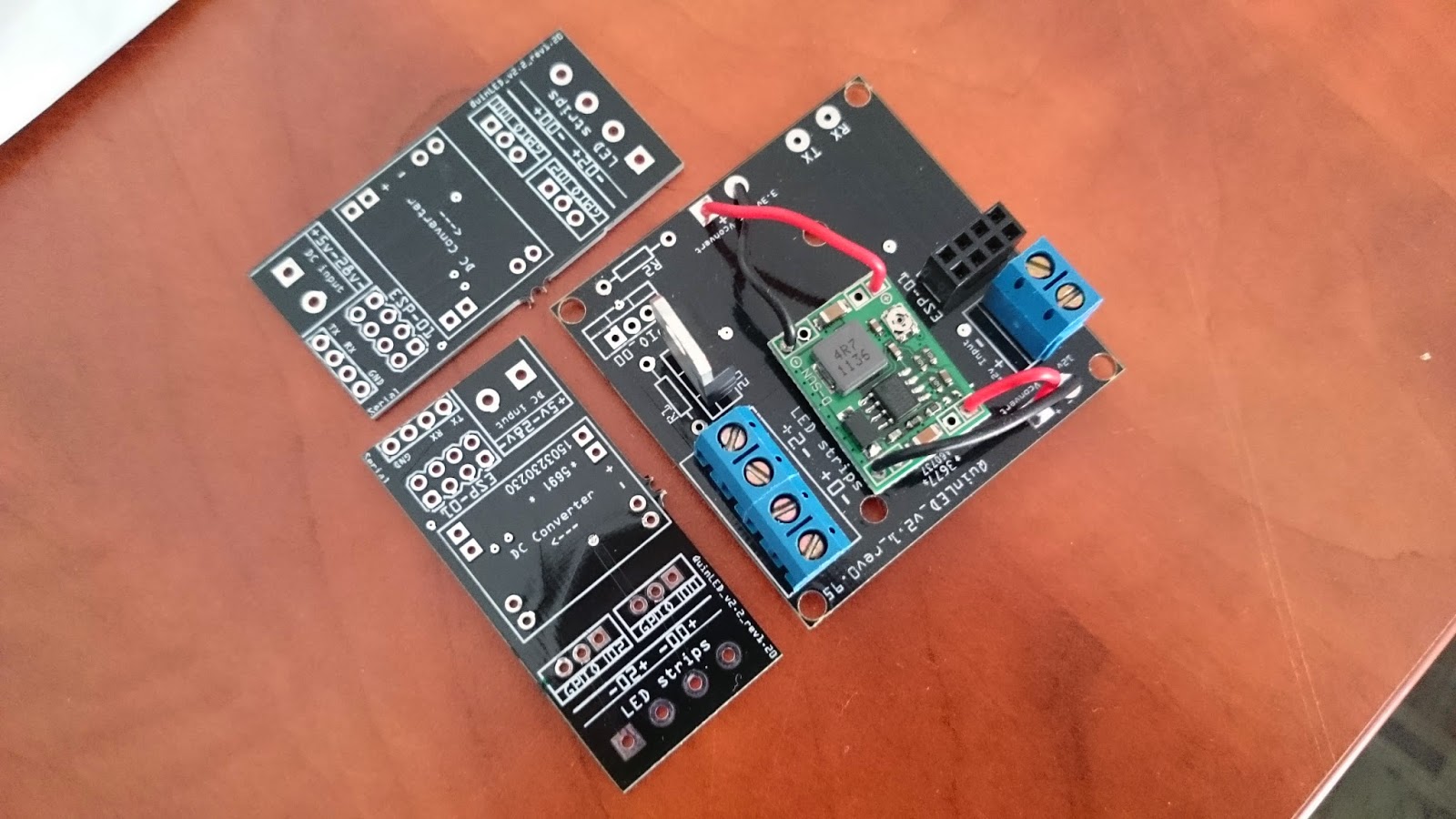
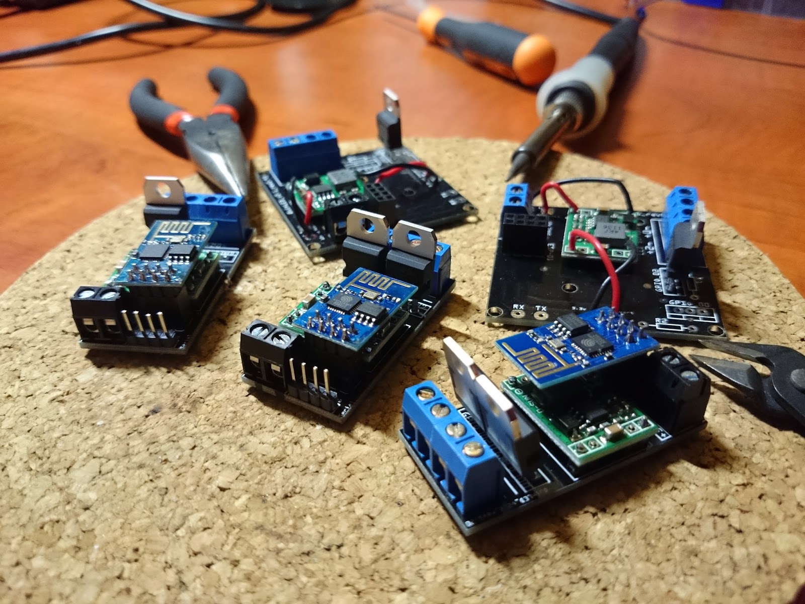
Three boards soldered and ready for testing, old boards in the picture to compare
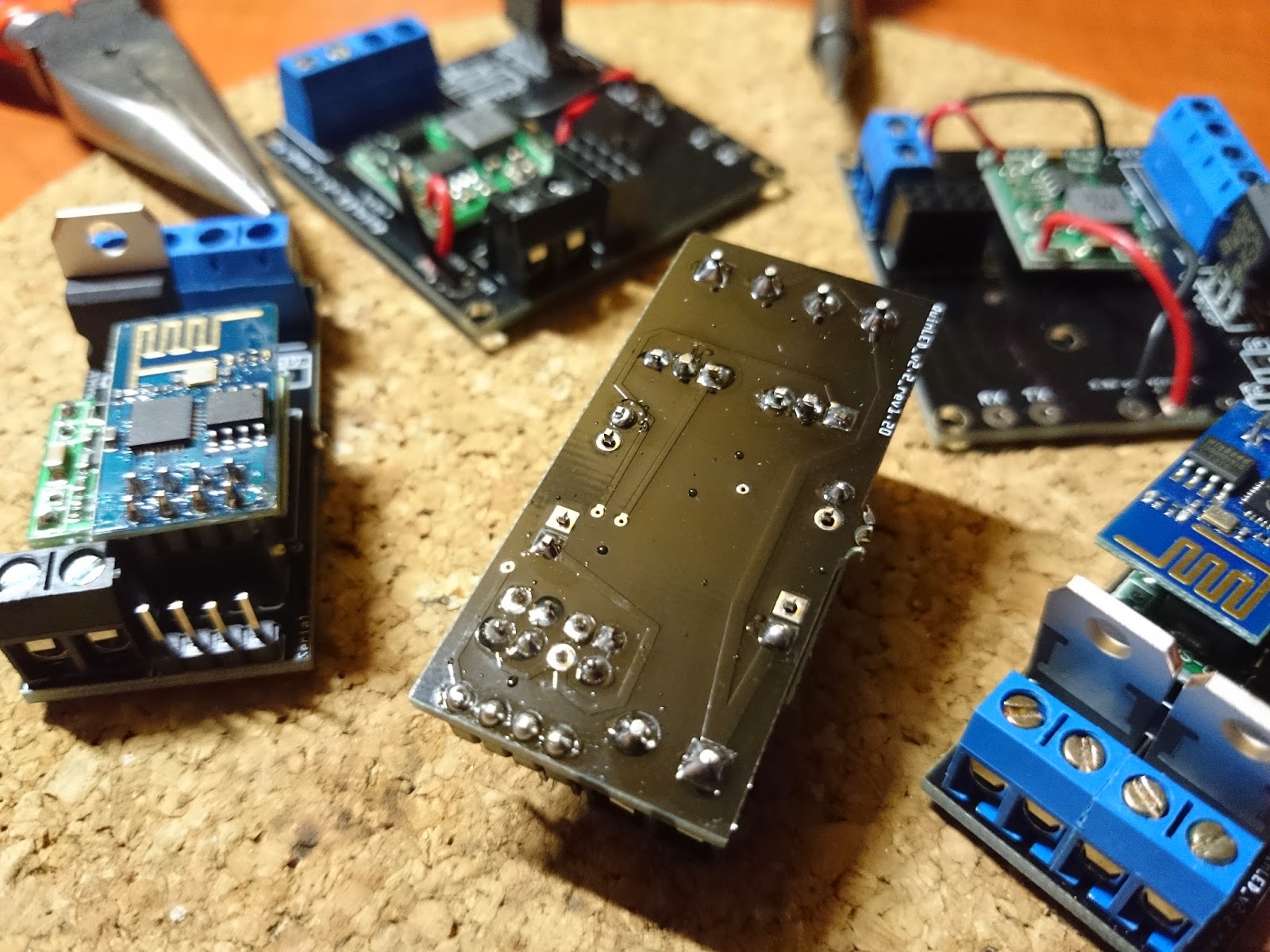
Backside of the board where all the soldering is done
“Instructions”
No real instructions are needed to solder the boards. All components used are clearly seen, a small list would be: (For convenience I linked everything to the Aliexpress links where I purchased the components)
–update 2017-02-07
This series has since had a reboot and new component lists + (video) tutorials (also soldering) are available! Check it out over here.
Best instructions I can give you is to make sure you solder small to big components. Start with the header pins, then the DC-DC converter, then the 2×4 header for the ESP-01 and last the wire terminals and then the MOSFET(s).
When soldering the MOSFET(s) in place, make sure there is a little bit of room between them so that they are not touching, that could potentially be bad. 😉 !Make sure you set the DC-DC voltage converter between 3.3v and 3.6v before connecting the ESP-01! Per default these DC-DC converts come set to about 12v. It will kill your ESP-01 very quickly!
If you wish to alter the design or do something else with it, that is fine by me too, I was only able to create all this by using stuff I found on the internet too. You can download the fritzing files using this link. Check out version 2.6 here.
To finish, some more pictures of the board ‘in action’!
