
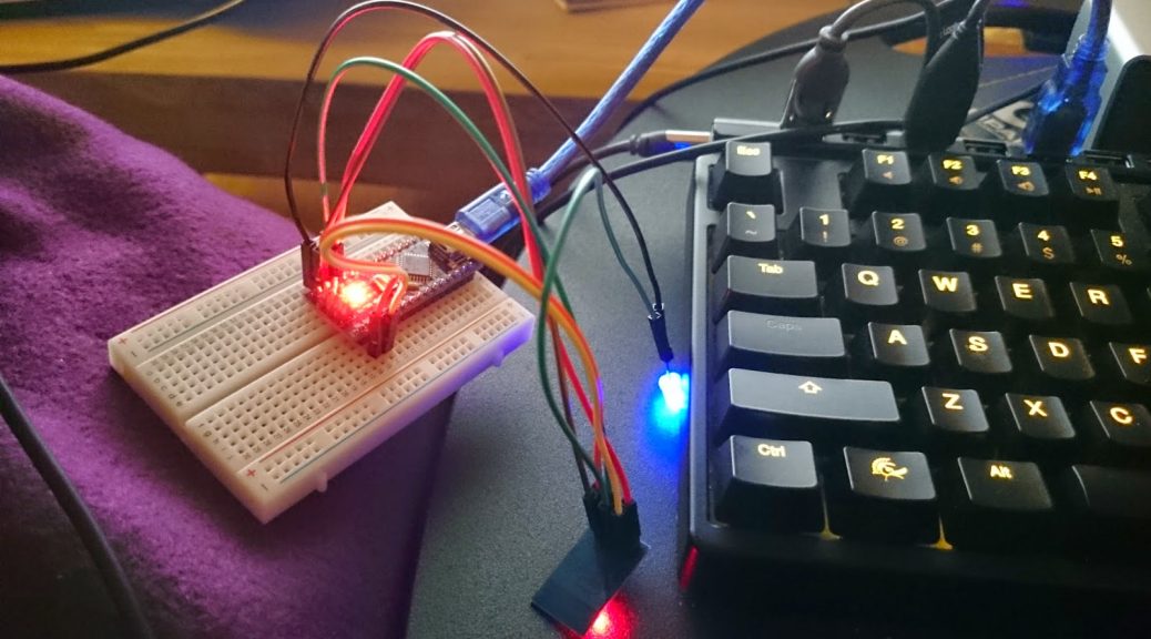
To get started with the ESP8266 ESP-01 I recommend flashing and programming it before soldering it down. This way you know it’s working and that the program code is also functioning. Depending on how you mount it on your board it can be a bit hard to do so later on!
This series has been rebooted
Please take a look at the following post to visit the new rebooted series and index of all posts: https://blog.quindorian.org/2016/07/esp8266-lighting-revisit-and-history-of-quinled.html/
Firmware flash mode
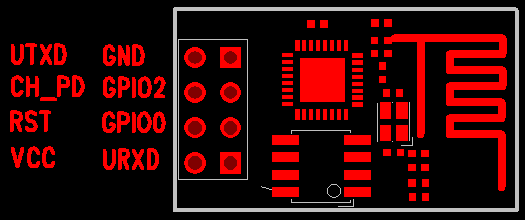
| Schematic overview of the ESP-01. Mind the orientation of the board, this is viewed from the top side |
Normal running mode
Since two pins need to be connected to 3.3v it’s easiest to either use a breadboard with some dupont cables or a screw connector block to multiply the connection.
Flash mode
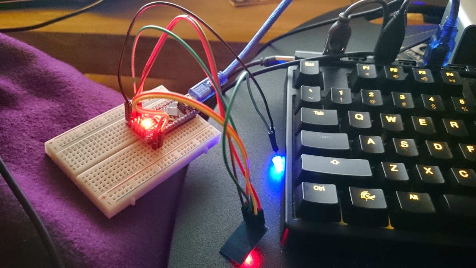
To get into firmware flash mode you need to make two additional connections, easiest is to use a screw connector block or breadboard for this.
Downloading the software
You should end up with a zip file with all the files in it. Extract it. The files we are looking for are located in the nodemcu-firmware-masterpre_build.9.4512k-flash directory and the file we are going to flash is nodemcu_512k_latest.bin
Sadly, this isn’t as easy as it was written here, it should be, but the 3 modules I flashed needed toying and trying again and again for about an hour each to actually get it to go into flash mode. Once it did there was no problem and it flashed just fine, but still it was a bit hard to get it do so sometimes. I still don’t know yet why it doesn’t always work the first time, it might be because I was using a 5v Arduino.
Installing the QuinLED program on the ESP-01
- node.restart(); – Restarting the ESP8266
- wifi.setmode(wifi.STATION) – Setting it to WiFi client mode
- wifi.sta.config(“SSID”,”PASSSSS”) – Connecting to your WiFi network
- print(wifi.sta.getip()) – Get the IP of the ESP8266
- wifi.sta.connect() – Connect to the set SSID
- wifi.sta.disconnect() – Disconnect wireless
- print(“Hello World!”) – Print some text
pwm.setup(3, 1000, 005)
pwm.setup(4, 1000, 005)
pwm.start(3)
pwm.start(4)

LED1_current=005
LED1_target=005
LED2_current=005
LED2_target=005

Fadetime1=5000
Fadetime2=5000

Stepcounter1=0
PosStepcounter1=0
DimTimer1=0

Stepcounter2=0
PosStepcounter2=0
DimTimer2=0

wifi.setmode(wifi.STATION)
wifi.sta.config("SSID","PASSSS")


srv=net.createServer(net.TCP)
srv:listen(43333,function(conn)
    conn:on("receive",function(conn,payload)

    print("Input:"..payload)

    if string.find(payload,"LED1") then
     LED1_target=tonumber(string.sub(payload, 13) )
     print("Received LED1 Target Value: "..LED1_target)

     Stepcounter1=(LED1_target)-(LED1_current)

     if (Stepcounter1) < 0 then
      PosStepcounter1=(Stepcounter1)*-1
      else PosStepcounter1=(Stepcounter1)
     end

     if (PosStepcounter1) == 0 then
      PosStepcounter1=(PosStepcounter1)+1
      else PosStepcounter1=(PosStepcounter1)
     end

     DimTimer1=(Fadetime1)/(PosStepcounter1)

     if (DimTimer1) == 0 then
      DimTimer1=(DimTimer1)+1
      else DimTimer1=(DimTimer1)
     end

      print (Fadetime1)
      print (Stepcounter1)
      print (PosStepcounter1)
      print (DimTimer1)
      print (LED1_current)
      print (LED1_target)


    tmr.alarm(0, (DimTimer1), 1, function()
     if LED1_current < LED1_target then
      LED1_current = (LED1_current + 1)
      pwm.setduty(3, LED1_current)
    elseif LED1_current > LED1_target then
      LED1_current = (LED1_current - 1)
      pwm.setduty(3, LED1_current)
    elseif LED1_current == LED1_target then tmr.stop(0)
     end end )
    end

    if string.find(payload,"LED2") then
        print("Received LED2 Target Value")
     LED2_target=tonumber(string.sub(payload, 13) )

     Stepcounter2=(LED2_target)-(LED2_current)

     if (Stepcounter2) < 0 then
      PosStepcounter2=(Stepcounter2)*-1
      else PosStepcounter2=(Stepcounter2)
     end

     if (PosStepcounter2) == 0 then
      PosStepcounter2=(PosStepcounter2)+1
      else PosStepcounter2=(PosStepcounter2)
     end

     DimTimer2=(Fadetime2)/(PosStepcounter2)

     if (DimTimer2) == 0 then
      DimTimer2=(DimTimer2)+1
      else DimTimer2=(DimTimer2)
     end

      print (Fadetime2)
      print (Stepcounter2)
      print (PosStepcounter2)
      print (DimTimer2)
      print (LED2_current)
      print (LED2_target)


    tmr.alarm(1, (DimTimer2), 1, function()
     if LED2_current < LED2_target then
      LED2_current = (LED2_current + 1)
      pwm.setduty(4, LED2_current)
    elseif LED2_current > LED2_target then
      LED2_current = (LED2_current - 1)
      pwm.setduty(4, LED2_current)
    elseif LED2_current == LED2_target then tmr.stop(1)
     end end )
    end
    end)
    end)

print ("Booted to QuinLED_ESP8266_V0.4")
When you have it pasted in ESplorer press the “Save to ESP” button to transfer it over. It will ask you for a filename and where to store it. The where is only a local place what the file will also be kept, the filename is important and I recommend you name it “init.lua”. That way it will automatically run when the ESP-01 boots.
The tool should now be pasting the code to the ESP-01 line per line and checking if it made it across intact. I sometimes have that the code will arrive corrupt and the tool will error. When that happens I recommend you give the ESP-01 a restart and then a WiFi disconnect command. Doing that always makes the ESP-01 much more stable for me and transferring the program shouldn’t be a problem.
Once the ESP-01 is programmed it might complain that it can’t start a second TCP server (it depends on what you where running or if you had some fail flashes). Just give the unit a reset.
Once it’s booted again you can use the above mentioned commands to ask for it’s IP. You should be able to ping that IP. Don’t be alarmed by it’s ‘not so great’ ping times, this is normal.
Issuing commands to the ESP-01 running QuinLED
echo LED1_target=1000 | nc ip.ip.ip.ip 43333
That should said GPIO0 to a duty cycle of 1000. A duty cycle can be anything in the range of 0 to 1023. Do not use a number higher then that because right now the program will crash. 😉 It’s no use anyway because the ESP8266 supports 1024 PWM duty cycle levels so 1023 is fully open.
And that should be it, you can now control both channels of the ESP-01 connected to your LED strip. In my next post I will explain how you can hook this up into Domoticz and give it control over both channels independently.
Congratulations with a very well written blog post, explained in good detail!
There is a small typo just after the Lua code. It should not say "Send to ESP", but "Save to ESP".
Thank You for your great guide !
I do have a problem though, instead of a led strip i use as a load a led street lamp that has 40 leds of 1W and is driven with a 30Vcc led driver.
My issue is that the leds never stay full on, they basically blink all the time, which is annoying.
Regardless of the duty cycle, i can see the code dimms the light but the leds are always blinking, coul dit be that the MOSFET can't sustain the gate open and cycles from closed to open ?
Any ideas ?
This comment has been removed by the author.
Thank you for your work! I have everything turned on, tune in, works.
Good to hear, enjoy!
When I have noticed this it was because the power supply was constant current and not constant voltage. Because of that the power supply keeps trying to adjust constantly in the range it can, but because of the PWM it becomes confused.
Best is to measure the voltage at full power, get a power supply to match that power supply, add in my board and then use PWM. I'm doing that with several LED lamps too and it works perfectly.
This really works well..Thank you. I'm trying to control my ledstrip and add a PIR sensor to this ESP module. Do you have any suggestions on how to get the sensor reading from PIR and send the output to the LED strip. So i guess the ESP will be listening for the LED output settings and should send PIR sensor data back to Domoticz?
Hi,
I have problem with upgrading firmware. Nothing fill-in when I press FLASH
Hi I get the following error while trying to send the command : echo LED1_target=1000 | nc ip.ip.ip.ip 43333 to the dimmer :
stdin:2: '=' expected near 'LED1_target'
I can't figure out why tis is happening, please help me
I am looking for Arduino IDE equivalent of the code, as for some reason, 2 of my ESP-01 chips refuse to run nodemcu, while running fine Arduino IDE programs.
No clue, I have not had that problem before. I have had ESP's which I re-used a few times and became less stable, but that's a whole different problem.
No clue, are you using esplorer to upload the code to your ESP? Also please use the code and nc line from the newer post.
Thenk you vey much!!! I was stucked flash my ESP01 until you show me that GPIO02 should be VCC.
Socat does not hang like nc, I recommend sending the brightness like this:
echo LED1_target=500 | socat – TCP:ip.ip.ip.ip:43333
Awesome project! I got my first one up and running today, including learing how to flash LUA on the esp8266.
There are 3 adjacent LEDs on my strip that randomly flash at different brightness levels when I set the brightness to 1023. At 1022 and below they act normal.
hii.. i am getting " waiting answer from ESP – Timout reached. Send aborted "
what should i do ?
That's odd, that would mean this would also happen is no dimmer is attached? Value 1023 is MAX open, no dimming applied.
I'll give that a try, thnx! 😀
Not sure what is going wrong there. Try hooking everything up again and see if it works then?
Not sure what is going wrong there. Try hooking everything up again and see if it works then?
I'll give that a try, thnx! 😀
That's odd, that would mean this would also happen is no dimmer is attached? Value 1023 is MAX open, no dimming applied.
Wonderful directory ideas that can help to boost our own web site creating, after i creating web site I will recall these points as well as help make some really good creating.ios 7 app design
Hi there! I know this is somewhat off topic but
I was wondering which blog platform are you using for this site?
I’m getting fed up of WordPress because I’ve had issues with hackers and I’m
looking at alternatives for another platform. I would be awesome if you could point me in the direction of
a good platform.
Ah, well…. I guess you didn’t read my first post, I actually just switched to WordPress… so can’t help you there. 🙁
Hi there.
I’m playing around with one of your boards, but it would seem that I can’t get full power coming through the MOSFET to the LED lights. I’m measuring 3.44 volts (what the voltage step-down module is set to) between the GPIO and the negative terminal, but I’m only getting ~7.6V on the LED outputs, I can definitely get the LED’s full power direct on the power supply.
I’m curious if maybe I got the wrong MOSFET’s and they require more voltage to turn on fully. I ordered STP16NF06L from aliexpress, and they are stamped with the “L” on the chips, but they could be miss-labelled (they are super cheap from china after all). Do you think this could be the cause?
P.S. I distinctly remember NOT using your link because I found a cheaper listing, so I feel that this might be the problem.
Awesome to hear you are using some of my boards! Sadly, you have a common issue with getting the MOSFETs from China. The one’s you receive probably need ~5v to fully open the gate.
A quick test you could do is raise the DC-DC voltage converter to 5v and see if that makes the MOSFET give more output power. It probably will but that will tell you that the one’s you got, aren’t fully triggering at 3.3v as they should. If that is the case, definitely raise a complaint with the seller and explain the problem. They probably know but try anyway.
The link I currently provide certainly isn’t the cheapest, but I’ve heard back from others that the MOSFETs they are getting are working correctly! Otherwise, see if you can maybe source them cheaper locally? Aliexpress is great but for these MOSFETs it seems very hit or miss. 🙁
Thanks,
You’re correct. I tested with 5V across the MOSFET and it works with full power then.
I’ve managed to find an online retailer here in Canada that sells them, I’ve also found “STP85N3LH5” from the same manufacturer that’s on sake and cheaper. Looking at the data sheet it would seem that it would also work (just with faster switching and higher current ratings, but still with the 2.5V gate threshold). I might give that one a try. I’ll let you know if it works.
Cool! Sad to hear you got bad MOSFETs, hopefully the new one’s work, do let me know! 🙂