

The next part I needed for my Domotica system was a way to have physical switches in my house which would run ‘virtual’ actions. Tonight I programmed the ESP LUA code to test this.
This series has been rebooted
Please take a look at the following post to visit the new rebooted series and index of all posts: https://blog.quindorian.org/2016/07/esp8266-lighting-revisit-and-history-of-quinled.html/
The Desired function
The software part of it was pretty easy to write. The hardware “end product” though has to be very small to fit into the normal wall sockets. It would be added behind a wall switch and contain an ESP8266 and a power supply all in the tiny box.
In the future I aim to design a special PCB combined with a very small power supply so it can easily fit inside a wall socket box.
The way I wanted this to work is that the switch only flips a virtual dummy switch inside of Domoticz and coupled to that, any other action can take place. That way, I can program the ESP8266 with the correct Domoticz switch IDX once and then when I wish to change the function, I can always do so from Domoticz and won’t need to change what’s running on the ESP8266 module.
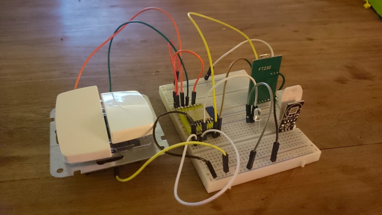
In my case I used a ESP-12 in this case. I recently received this version and when I got it to work in my breadboard I used that setup. It doesn’t matter which ESP8266 module you wish to use yourself, just be sure to change the pin numbers accordingly.
How it works
My code is currently configured to use two GPIO pins of the ESP8266. If you wish to run multiple switches using a single ESP8266 you will need to use as many GPIO pins as you want switches.
The wiring of the switch is easy. In my case the switch had a negative/ground in and two outputs, which get switched. I wired the negative/ground to the switch input and wired the outputs to the GPIO pins on the ESP8266.
The way it’s setup is that the GPIO pins will be HIGH by default (The ESP8266 will pull it high internally) but when the negative/ground is switched on the circuit will be connected and so it will go LOW because now it’s connected to ground. That state change is what we are looking for. The pin will remain LOW until the switch is flipped again. Each position will keep it’s respective HIGH or LOW.
The code automatically detects when a switch was switched and when it’s still in the same state so that it won’t continuously hammer Domoticz. That does mean that when the action associated with the switch is run manually on the web interface of Domoticz, it could be that nothing happens.
Example: If you turn the switch on using the physical switch, but then turn it off using the Domoticz interface, the actions associated to this will be carried out, but the physical switch will remain in it’s position. When you then flip the switch, you will be switching it to off again, so nothing will happen. To turn the light on, you will have to flip the physical switch to on, and the connection actions will take place.
With that in mind, let’s continue!
ESP8266 code
Currently the alarm loop is set to read the switch state every 0.1 of a second. This makes the reaction of the switch almost instant, but going through WiFi, then through Domoticz to another WiFi ESP8266 which then switches the light on has a little time delay. In my testing this delay was around 0.5 seconds or so, quite acceptable for my purpose.
Be sure to change the pins to your ESP layout!
update 2015-03-03
I updated the code so we now have variables for the most common settings and also added the code for connecting two separate switches. I also removed some logging so it won’t keep spamming the console with messages.
GPIOpin1 = 5
GPIOpin2 = 6
DomoticzIP = "10.10.128.14"
switchidx1 = 42
switchidx2 = 42
print "Vars set"
gpio.mode((GPIOpin1), gpio.INPUT, gpio.PULLUP)
gpio.mode((GPIOpin2), gpio.INPUT, gpio.PULLUP)
print "Pins set"
wifi.setmode(wifi.STATION)
wifi.sta.config("Q-LAN","yoloyoloyolo")
print "WiFi set"
print "Reading button states in loop"
tmr.alarm(0, 100, 1, function()
if gpio.read(GPIOpin1) == 0 then
-- print ("Button 0 = On")
if Switch0 == "On" then
-- print ("Switch already on")
else
Switch0 = "On"
conn=net.createConnection(net.TCP, 0)
conn:on("receive", function(conn, payload) print(payload) end)
conn:connect(8080,(DomoticzIP))
conn:send("GET /json.htm?type=command¶m=switchlight&idx=" .. (switchidx1) .. "&switchcmd=On&level=0 HTTP/1.1rn")
conn:send("Host: " .. (DomoticzIP) .. "rn")
conn:send("Accept: */*rn")
conn:send("User-Agent: Mozilla/4.0 (compatible; esp8266 Lua; Windows NT 5.1)rn")
conn:send("rn")
print ("SWITCHED Switch0 ON")
end
else
-- print ("Button 0 = Off")
if Switch0 == "Off" then
-- print ("Switch already Off")
else
Switch0 = "Off"
conn=net.createConnection(net.TCP, 0)
conn:on("receive", function(conn, payload) print(payload) end)
conn:connect(8080,(DomoticzIP))
conn:send("GET /json.htm?type=command¶m=switchlight&idx=" .. (switchidx1) .. "&switchcmd=Off&level=0 HTTP/1.1rn")
conn:send("Host: " .. (DomoticzIP) .. "rn")
conn:send("Accept: */*rn")
conn:send("User-Agent: Mozilla/4.0 (compatible; esp8266 Lua; Windows NT 5.1)rn")
conn:send("rn")
print ("SWITCHED Switch0 OFF")
end
end end )
tmr.alarm(2, 100, 1, function()
if gpio.read(GPIOpin2) == 0 then
-- print ("Button 0 = On")
if Switch1 == "On" then
-- print ("Switch already on")
else
Switch1 = "On"
conn=net.createConnection(net.TCP, 0)
conn:on("receive", function(conn, payload) print(payload) end)
conn:connect(8080,(DomoticzIP))
conn:send("GET /json.htm?type=command¶m=switchlight&idx=" .. (switchidx2) .. "&switchcmd=On&level=0 HTTP/1.1rn")
conn:send("Host: " .. (DomoticzIP) .. "rn")
conn:send("Accept: */*rn")
conn:send("User-Agent: Mozilla/4.0 (compatible; esp8266 Lua; Windows NT 5.1)rn")
conn:send("rn")
print ("SWITCHED Switch1 ON")
end
else
-- print ("Button 0 = Off")
if Switch1 == "Off" then
-- print ("Switch already Off")
else
Switch1 = "Off"
conn=net.createConnection(net.TCP, 0)
conn:on("receive", function(conn, payload) print(payload) end)
conn:connect(8080,(DomoticzIP))
conn:send("GET /json.htm?type=command¶m=switchlight&idx=" .. (switchidx2) .. "&switchcmd=Off&level=0 HTTP/1.1rn")
conn:send("Host: " .. (DomoticzIP) .. "rn")
conn:send("Accept: */*rn")
conn:send("User-Agent: Mozilla/4.0 (compatible; esp8266 Lua; Windows NT 5.1)rn")
conn:send("rn")
print ("SWITCHED Switch1 OFF")
end
end end )
Extra
wifi.setmode(wifi.STATION)
wifi.sta.config("Q-LAN","yoloyloyloyloylo")
print "WiFi set"
print "Reading button states in loop"
gpio.mode(5, gpio.INT, gpio.PULLUP)
gpio.trig(5, "both", function(level)
if level == 1 then
-- print ("Button 0 = On")
if Switch0 == "On" then
-- print ("Switch already on")
else
Switch0 = "On"
conn=net.createConnection(net.TCP, 0)
conn:on("receive", function(conn, payload) print(payload) end)
conn:connect(8080,'10.10.128.14')
conn:send("GET /json.htm?type=command¶m=switchlight&idx=42&switchcmd=On&level=0 HTTP/1.1rn")
conn:send("Host: 10.10.128.14rn")
conn:send("Accept: */*rn")
conn:send("User-Agent: Mozilla/4.0 (compatible; esp8266 Lua; Windows NT 5.1)rn")
conn:send("rn")
print ("SWITCHED IT ON")
end
elseif level == 0 then
-- print ("Button 0 = Off")
if Switch0 == "Off" then
-- print ("Switch already Off")
else
Switch0 = "Off"
conn=net.createConnection(net.TCP, 0)
conn:on("receive", function(conn, payload) print(payload) end)
conn:connect(8080,'10.10.128.14')
conn:send("GET /json.htm?type=command¶m=switchlight&idx=42&switchcmd=Off&level=0 HTTP/1.1rn")
conn:send("Host: 10.10.128.14rn")
conn:send("Accept: */*rn")
conn:send("User-Agent: Mozilla/4.0 (compatible; esp8266 Lua; Windows NT 5.1)rn")
conn:send("rn")
print ("SWITCHED IT OFF")
end end end )
Nice. Did you also did something with debouncing? With mechanical switches it is quite important to do so, i learned from playing with Arduino's. As you close the circuit (switch = on), when the switch is almost closed it will trigger between on/off/on/off/on. Maybe implement a delay of 200ms or so?
And i also like the rest of your ESP8266 tutorials, i'm still waiting for the day you will write a tutorial on how to drive an RGB LED-strip with an ESP8266 (ESP with min. 3 GPIO) and Domoticz…. *hint*
Hi, thnx!
I have not implemented any debouncing. I have not seen this phenomenon happening yet, but it might be something that comes with age of the switch? My test switch has a very definitive "click". Also I think Domoticz might actually buffer it a little bit so it wouldn't even be a problem?
If I do encountered the problem, adding a little delay after it sends the Domoticz switch command is easy!
About building an RGB version. Don't hold up your hopes, it's not what my intended usage scenario is really. With traditional strip it would mean adding a third mosfet and I find mostly I'm not even using a second one! You could easily do it yourself though?
But about RGB LEDs, what I am going to do at some point (I already have all the materials) is write a tutorial on how to drive a Pixel Addressable RGB LED strip. Although the strip will be more expensive, you won't need a mosfet or anything like that! More on that later on.
Anyhing more on driving the Pixel addressable led strips ? I’m considering doing this as well, but I would use to, not only, change color as a whole, but make some special programs (christmas style for example) as well.
It’s a future project for sure but when… I have no clue. 🙁
How about using interrupts for detecting on/off events instead of polling? NodeMCU has the gpio.trig() function which you can use like this:
gpio.mode(5, gpio.INT, gpio.PULLUP)
gpio.trig(5, "both", function(level)
if level == 1 then
// changed to on
else
// changed to off
end)
This would probably improve the reaction time a bit.
Hey, that looks a lot better, awesome!
I'll test it tonight and then update the code here if it works just as well! 😀
I tried your suggestion and while it works, it doesn't work consistently. From every 10 switches, 9 work and just sometimes it misses 1! When that happens, the switch actually reverses function, so the top position of the switch is then off and the bottom on. 10 clicks later, it reverses again. Really weird since it's reading ground or not. :S
Going back to the script above I tried a 100 switches after each other, not a single one missed.
So I don't know what is going on, in theory it should work just as well, in practice that isn't the case!
I'm currently running Build 20150213 on a ESP-12
Great instruction!
1. Maybe its necessary to have an anti-bounce when used with the interrupts. Capacitor to the switch?
2. Do the GPIO like it when they are connected directly without a resistor?
Hi Quindor,
Thanks for this wall switch tutorial. I was looking for something like this a long time for replacing my kaku remote controls.
Unfortunately i have the following problem when i use your code for the esp8266 (with changed network and switch idx), this is what happens: when i operate the switch i see the text "SWITCHED Switch1 ON" (or OFF), the esp8266 is sending (blue light) and in the Domoticz log i see an incomming connection from the esp8266. But the switch state in Domoticz is not changed.
Can you tell me what i do wrong? It's maybe a stupid question but my programming skills are not as good as my hardware skills.
Hi,
I'm having the same problem with missed interrupts. I've not found a solution yet which is a shame as the .trig would enable much cleaner code…
Hi quindor,
I lik your series on the esp 8266. I'm also experimenting with the 8266 boards (esp-03). I already built a two channel mains switch prototype which I use to control my projection screen. My blogs are on http://www.huisbesturing.nl (they ate in dutch however) if you are interested. My goal is also to build a single channel unit that fits inside a wall socket box. I'm basing the power unit on the lnk306pn. The power supply will be not isolated, but I'm also writing software that can be updated over the wifi connection, so after an initial download of the software (before connecting to mains), no phycical connections are needed. This is also handy because you can leave the unit in the wall socket when you feel the urge to change the software.
Isn't this the result of the type of interrupt you choose? With Arduino you can choose different types of interrupt on which it should trigger. Look here: http://arduino.cc/en/Reference/attachInterrupt (under 'Parameters' > 'mode'). The code you tried watches for both kinds (high/low), maybe try with only 'low' ? (GPIO pulled to GND = switch on for example).
I think it will work more stable then. In theory the interrupt part is better, because it uses less CPU. Also if you want to create a battery-operated switch it is better to use interrupts, you could put the ESP8266 to sleep, and wake it by interrupt. Your current (loop-based) code can't do that 😉
This comment has been removed by the author.
This comment has been removed by the author.
Hi all,
Amazing tuto Quindor.
I'm learning a lot to start to play with my esp8266. But at this point. What about the script for domoticz to interactive with the swiches. I'm reading and reading documentation but nothing found about it.
Thanks for your help.
Hi Raul,
Thnx for the praise! 😀
I'm not really sure what you are talking about the Domoticz script? In Domoticz you don't need a script!
In Domoticz you create a virtual switch of which you then input the IDX into the ESP8266 code. From that point forward you will be able to flip the physical switch and the virtual Domoticz switch will follow it.
Then in Domoticz you create a blocky (drag and drop) to connect consequences to the switch being up or down. So it can influence another switch, or several others, whatever you want!
Hopefully that helps!
Is it maybe more handy if you make it a toggle? I don't know how to program, but:
———
state = 0
Loop () {
if gpio.read(GPIOpin1) != state then
state = gpio.read(GPIOpin1)
"send commando to domoticz"
wait (200)
}
—–
This comment has been removed by the author.
It would look a bit like this:
Switch0 == 0
print "Reading button states in loop"
tmr.alarm(0, 100, 1, function()
if gpio.read(GPIOpin1) != Switch0 then
— print ("Switch 1 State changed")
Switch0 = gpio.read(GPIOpin1)
conn=net.createConnection(net.TCP, 0)
conn:on("receive", function(conn, payload) print(payload) end)
conn:connect(8080,(DomoticzIP))
conn:send("GET /json.htm?type=command¶m=switchlight&idx=" .. (switchidx1) .. "&switchcmd=Toggle&level=0 HTTP/1.1rn")
conn:send("Host: " .. (DomoticzIP) .. "rn")
conn:send("Accept: */*rn")
conn:send("User-Agent: Mozilla/4.0 (compatible; esp8266 Lua; Windows NT 5.1)rn")
conn:send("rn")
print ("SWITCHED Switch0 Toggle")
end
end )
Not equal is ~=
First of all, congratulations on the dimmer. I am going to replicate it. Now on the MOSFET, why do you ned both in the design and how are you not using both?
And finally, what is your progress on Pixel Addressable LEDs?
I might also have a solution for small power supply, just waiting to receive it and test myself.
The two MOSFETs are there because I'm using the dimmer modules with 2 channels. So you can use one ESP dimmer module to independently regulate two lights. If you only wish to use it for one, or multiple lamps but don't have the need to set them independently then using one MOSFET is fine.
Another reason can be power requirements. One MOSFET can be used to run about 3A or 4A pulsed without problems. If you desire more, best to use another MOSFET because of heat dissipation.
Thank you for prompt reply. I have seen on one of the photos a board with one MOSFET and was curious.
On the power supply, check this one: http://lygte-info.dk/review/Power%20Mains%20to%205V%200.6A%20Hi-Link%20HLK-PM01%20UK.html It has been recently tested and looks good also for putting in the wall and the price is really reasonable.
When we press the switch is safely connect GPIO directly to the ground without resistance?
Pacitzu
I really love this idea of repurposing the wall switches.
Did you achieved this, or gave up of the project?
The wall switches was always a prototype/test and it worked well. I haven’t gotten around to doing anymore more with it but I’m planning to do so in the future when I’m in the new house!
I was thinking of using a similar approach as you did, however on this page i do not have the wiring diagram you used as well how did you connected your wall switches. I’ve been researching and trying to find a solution for a long long time, without any success. If you have the time would it be possible to share more details on how you achieved this?
Furhtermore i know that the wall switches usually work at 220v but in your solution i think you connect ground and 3.3v directly to the wall switch does it actually work, to get the status on the wall switch?
I am working on something similar, only just on and off, and using really low cost hardware. So this is using an ESP8266-1, and the guts from a small 3.3V wall wart, and a single channel relay board, and a momentary push button switch.
GPIO0 runs the relay. This code for this is exactly like the reference code on the net for controlling an LED via a web browser.
GPIO1 reads the switch. This is a momentary switch. When you push it, it jumps to a function that reads the status of the GPIO0 line, and inverts it. So if GPIO0 was high, it will go low, and if it was low, it will go high. You can turn the relay on and off via the web interface or the local switch.
How were you going to deal with the dimming?