


It’s been about 1,5 to 2 years since I started the project to create my own wirelessly controlled PWM LED dimmer. Since that time I’ve kept refining the PCB and code and this post will be a sort of revisit and revision history of QuinLED.
In future posts and videos we will be doing a new tutorial on what components you need, how to solder it all together, program the ESP8266 and link it to Domoticz. I also plan to create posts about the LED Power wall I’m going to build to house everything centralized in my house.
–2019 update–
I’ve been working on new QuinLED modules and they have recently been released. To make all the content surrounding the new dimmers and everything LED easier to find I’ve started http://quinled.info as a sister website to this one!
There you can find the newly released QuinLED-Quad and QuinLED-Deca modules, improving upon a lot of features compared to the now called QuinLED-OG! This doesn’t mean the QuinLED-OG isn’t a viable solution anymore, hundreds of modules are still being used each day and it’s still the smallest and by far the cheapest design.
In 2019 I will also be releasing Digital Controllers for addressable LED strip and LED panels, more about that on the new website!
So check out the new website and then decided which dimmer best suits your needs!
http://quinled.info
More in this series
- ESP8266 LED Lighting: Revisit and history of QuinLED (This post)
- ESP8266 LED Lighting: Board files and components list
- ESP8266 LED Lighting: QuinLED soldering tutorial & Tools
- ESP8266 LED Lighting: Setting voltage and flashing NodeMCU
- ESP8266 LED Lighting: Programming and controlling QuinLED
- ESP8266 LED Lighting: QuinLED v2.6 PCB
- ESP8266 LED Lighting: Installing COB LED downlights controlled using QuinLED
- ESP8266 LED Lighting: Using QuinLED with Domoticz
- ESP8266 LED Lighting: Outdoor Wall/Garden Cube LED lights
Be sure to also checkout
Old series about my ESP8266 dimmer
- ESP8266 WiFi LED dimmer Part 1 of X: The setup
- ESP8266 WiFi LED dimmer Part 2 of X: The Hardware
- ESP8266 WiFi LED dimmer Part 3 of X: Flashing and programming the ESP-01
- ESP8266 WiFi LED dimmer Part 4 of X: Configuring Domoticz
- ESP8266 WiFi LED dimmer Part 5 of X: Ikea Lamp hacks
- ESP8266 WiFi LED dimmer Part 6 of X: ESP8266 Domoticz Wall Switch
- ESP8266 WiFi LED dimmer Part 7 of X: Updated Dimmer and Domoticz code
- ESP8266 WiFi LED dimmer Part 8 of X: Version 2 of the PCB design
- ESP8266 WiFi LED dimmer Part 9 of X: The new house lighting plan
- ESP8266 WiFi LED dimmer Part 10 of X: Finding the right lights
Video
The video basically says it all. Go and watch it!

What is it, how does it work?
As I said in the video, in one sentence, it’s a ESP8266 based PWM WiFi controllable dimmer. That’s a whole lot of acronyms in one sentence, so I’ll try and explain each of them desperately.
ESP8266
The ESP8266 is a micro-controller like you might know an Arduino or a Pix. These are small computers which are programmable to carry out certain tasks. They are most often tasked to handle controlling simple functions inside of a device.
In our case, the ESP8266 creates the WiFi connection and runs the program that, depending on the input value it receives, dimms the connected LED lights to the desired intensity level.
We use the two GPIO pins that the ESP8266 has to pulse the MOSFETs.
PWM
As I explained in the video, PWM is a method of digitally controlling a signal. In my case I use it’s properties to dimm the connected LED lights.
My program in the ESP8266 pulses it’s GPIO’s a 1000 times per second. The width of the pulse determines the resulting light intensity. That all sounds a bit technical, but maybe this diagram can explain it a bit better:
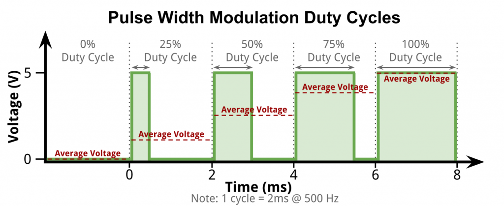

Pulse width modulation
Although the GPIO pins on the ESP8266 generate the pulsed signal, the MOSFETs amplify this at the original voltage and handle all the current.
MOSFETs
A MOSFET is basically a gate that can be switched on and off very quickly. The ESP8266 can only handle very low amperages at 3.3v, enough to light of a single low-power LED a bit, but certainly not more then that.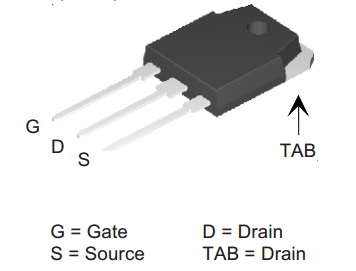

The MOSFETs I use have three pins. Input, Output and a gate. Basically, my PCB connects the incoming 12v, 24v or 36v (or anything in between really, my design needs 5v at the lowest) to the input pin and connect the output pin to the LED lights.
The gate is connected to one of the GPIO ports on the ESP8266 and that’s, in simple terms, how the whole design works!
What do I plan to do with it?
The whole inspiration behind this project is because I believed commercial LED dimmers are too expensive and don’t offer the features I desired.
Since this is a custom solution which is software controlled, we can make the connected lights do anything we desire!
Because of that, in later code, I added an auto-calculating dimming algorithm which you can tell how long it should take to fade from [current value] to [target value]. This makes for automatic and slow of fast smooth transitions, depending on what you need!
If you are interested in where these lights are going to go in the house, take a look over here.
And if you are interested to see which lights I selected, read the article over here!
And everyone who is interested to see how far the house has progressed up until this point, check out this post and this post.
Next article
The next article will be about the hardware you need, the QuinLED board and how to solder it all together!
If you have any questions or comments, please leave them below or under the YouTube video!
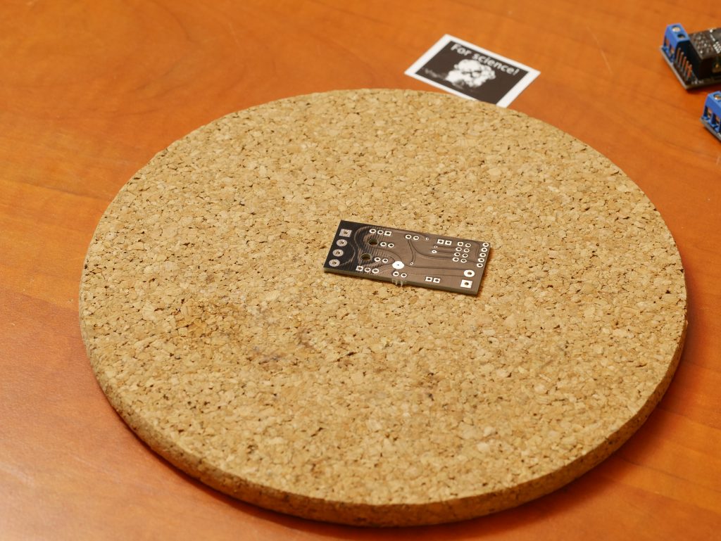
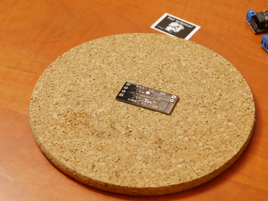
Revision Photos
Prototype board
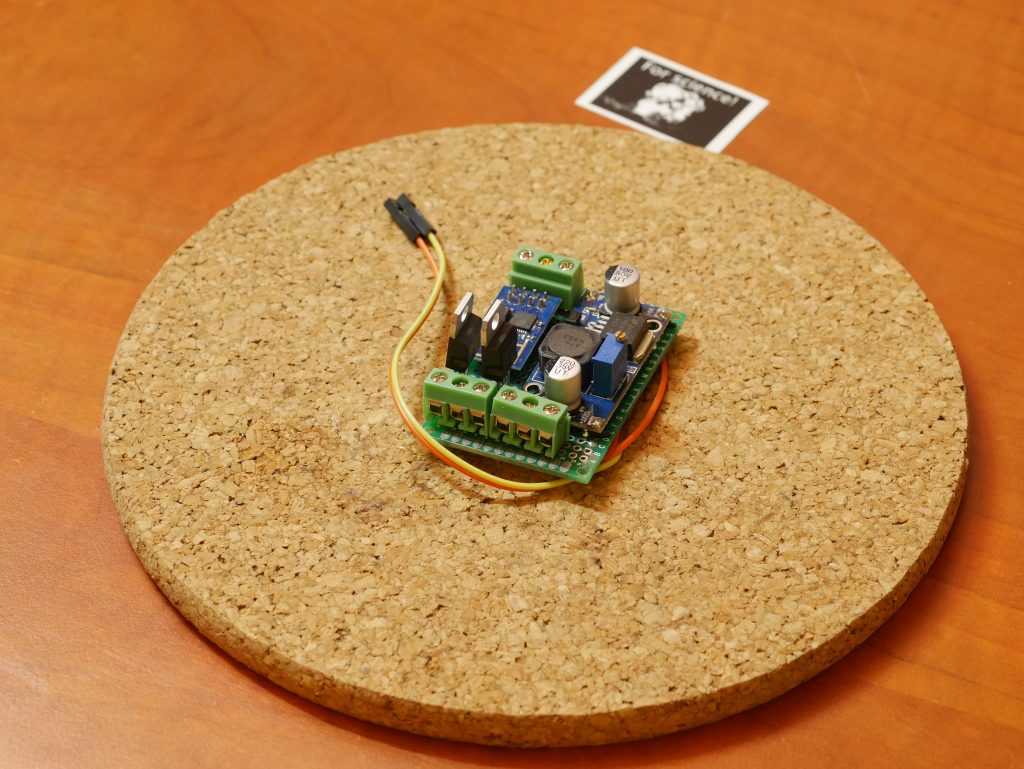
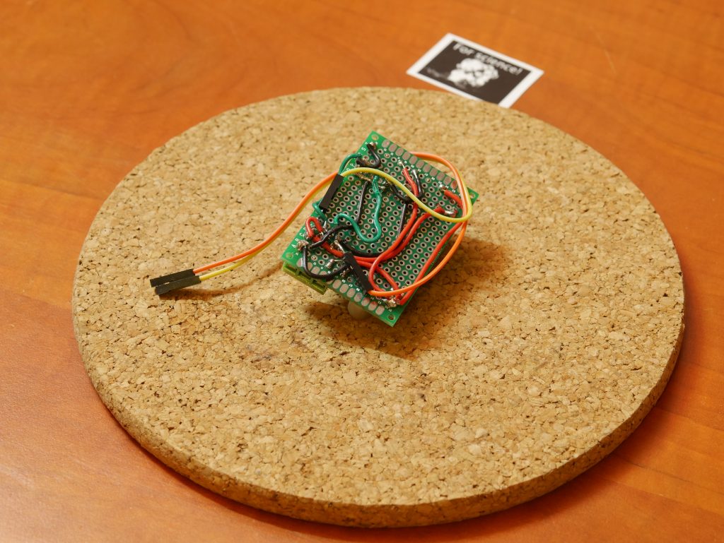

Version 1 PCB
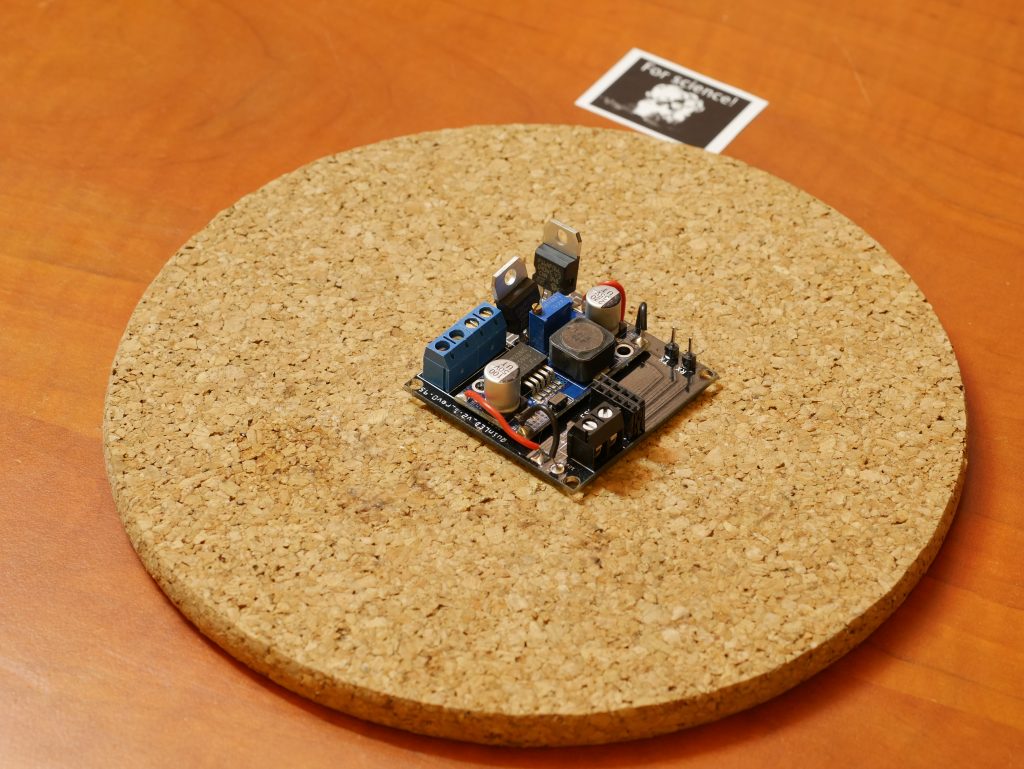
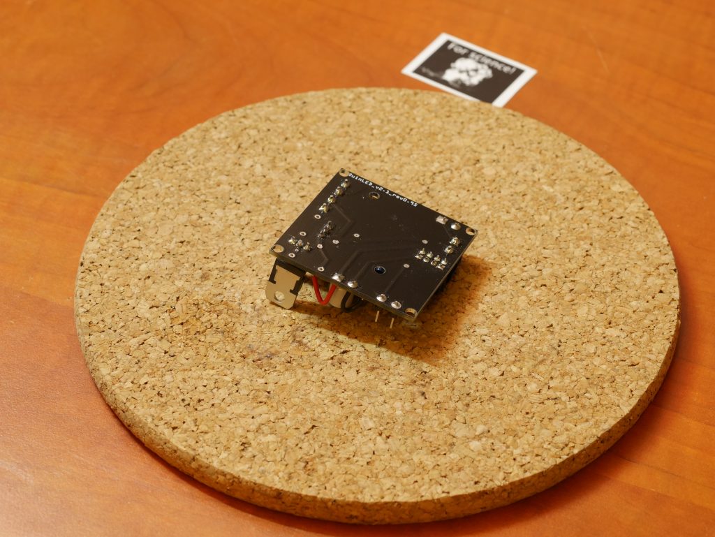
Version 2 PCB
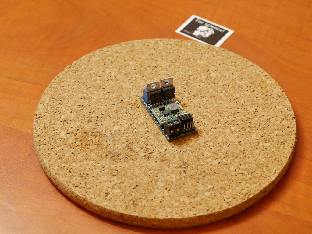
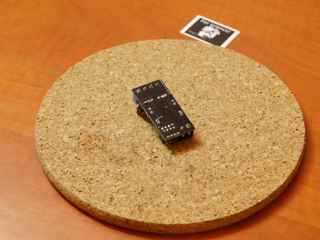
Version 3 PCB
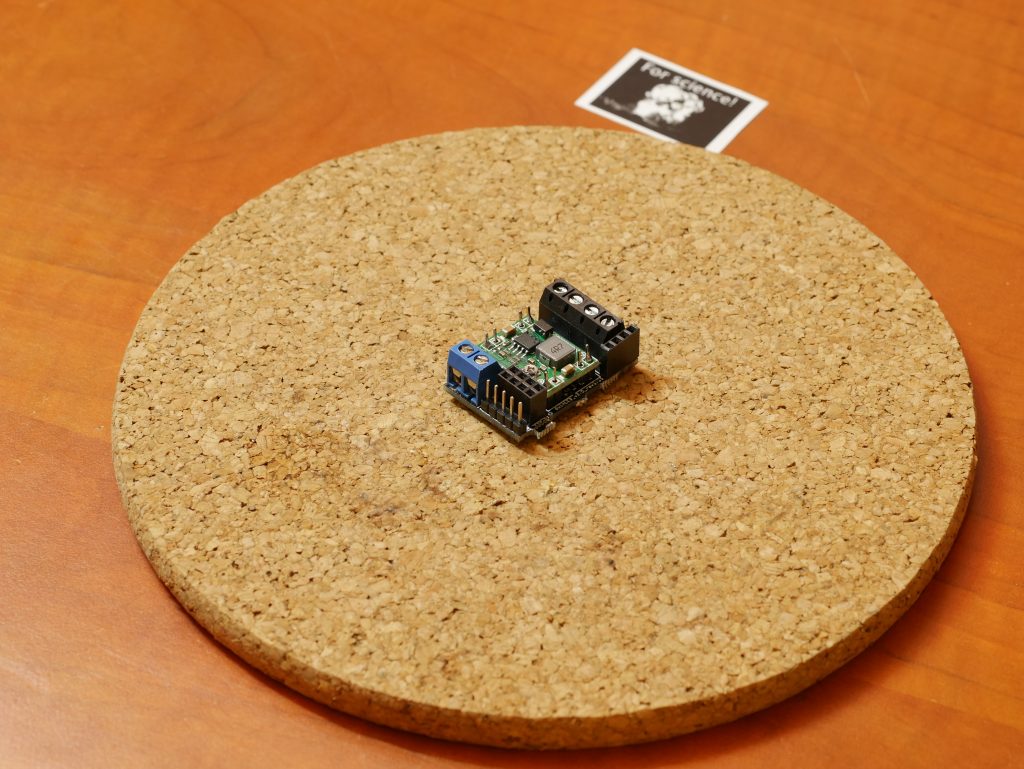
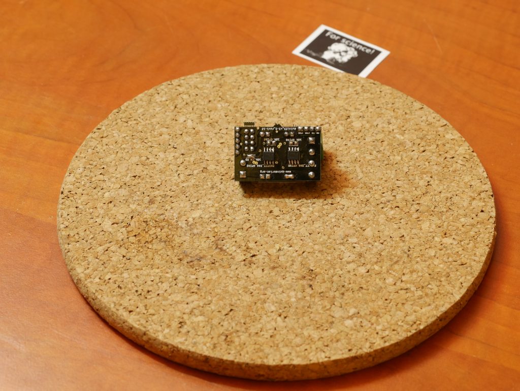
Version 2.5 rev 1.00
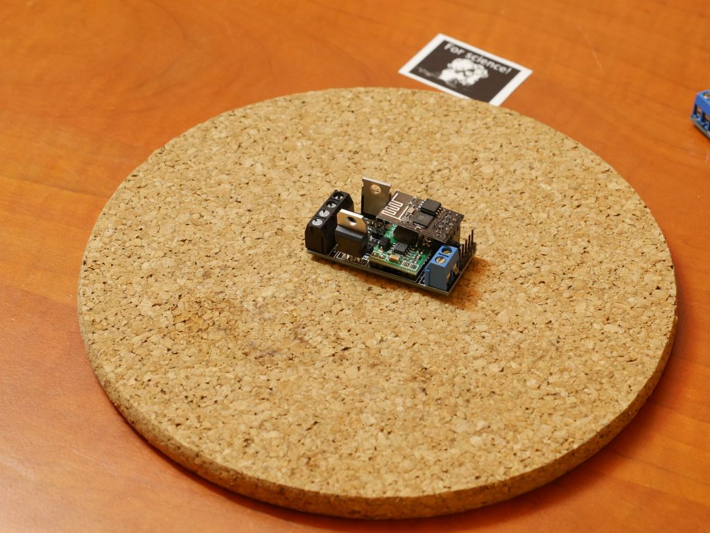
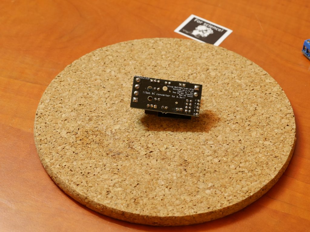
Version 2.5 Rev 1.12
Version 2.6 rev 1.00
Check the articles in the top of the post, version 2.6 is now available and I recommend anyone getting started getting that version!
Old Article
As I mentioned, this is more of a revisit of the project I started about 2 years ago. If you would still like to read the original article, you can find it here.