With the help of kind internet folks I was able to get a fritzing part for the new voltage converter I wanted to use to try and make a smaller board. A few weeks ago I sent my new ‘panalized’ design to dirtypcb’s and I got them back last week. They are awesome! Read on to order the boards yourself!
–update 2017-02-07
The need for a smaller board
The first design of the QLED dimmer was my amateur attempt to create a PCB board with the components I had at the time. And while it works just fine, some things in the design I really wasn’t very happy with.
So, I set out to design a new v2 board and improve on all those things and also try to make it as small as possible.
v2 managed to do this! It is very small and keeps all the features of the v1 board except for the resistor spots. I really see no practical use for them and all my boards have been functioning just fine, for months, without them.
The reason why I wanted to make the board smaller is because I want to use them inside of electrical sockets inside my house. I’m not yet completely sure of how I’m going to accomplish this (Mostly I am in need for a small power supply) but having the board fit is the first part at least.
The new board
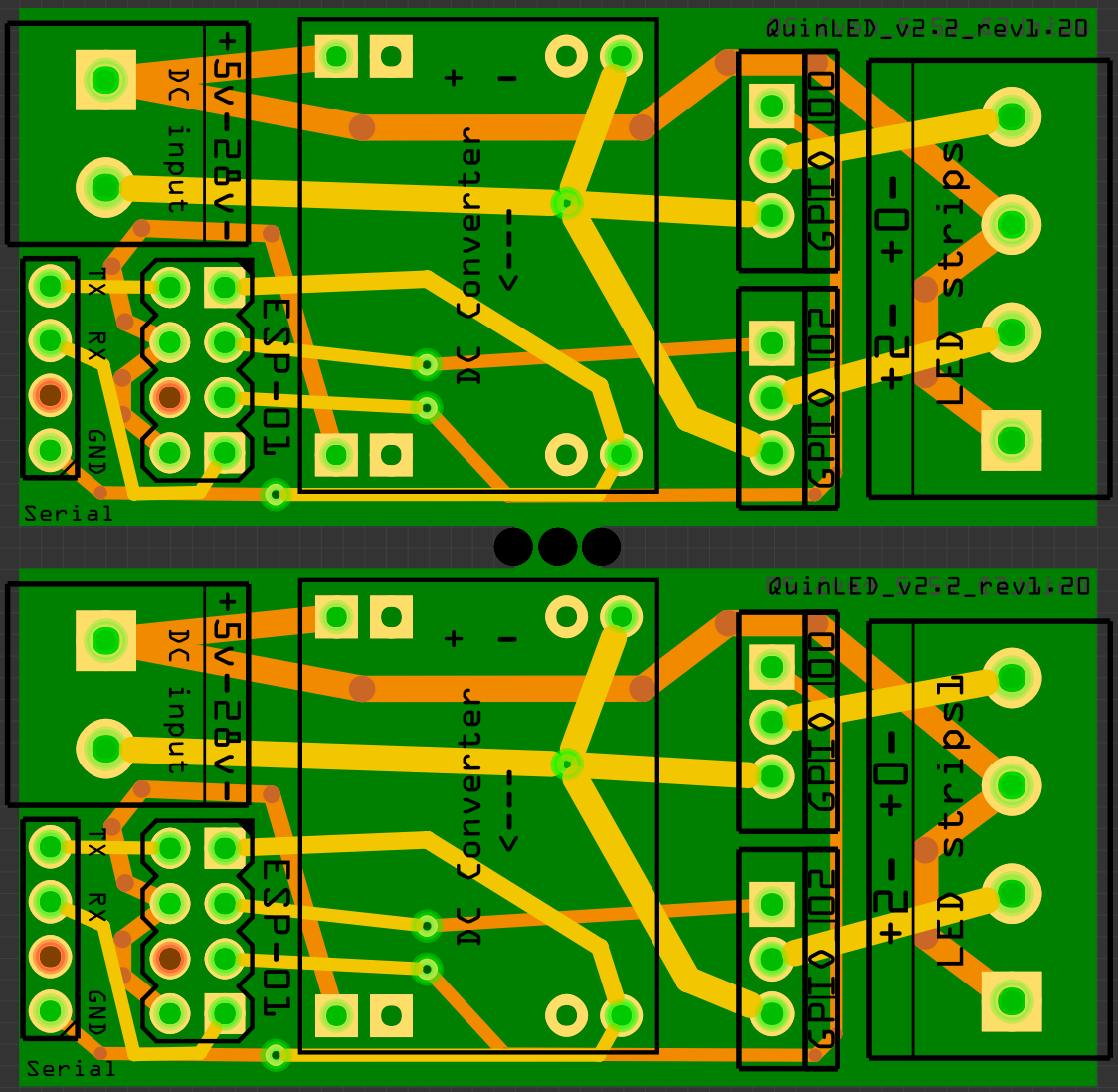
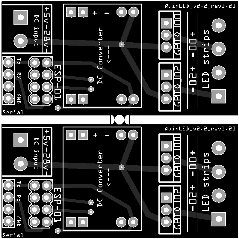
The new board measures 50mm x 23mm in total. So basically it’s v1 cut in half. This opened up an interesting option. DirtyPCB allows you to use a panalized design for your PCB’s. What this means is that a router can cut your PCB in shapes, at no extra costs.
That led me to design it as following:
 |
| Panalized design |
Basically you create a custom SVG file which becomes your board shape in the end. This means that the 10 to 12 boards you get from dirtyPCB’s for 14$, now become 20 tot 24 boards! v1 was already cheap, but v2 is half (in PCB costs). Incredible value!
Since I wanted to be able to break the boards apart easily I made the computer create some drill holes in the middle, leaving only a little bit of PCB connected together. This works perfectly.
I also took some time to improve upon the first board such as lining up the + and – connections on both sides of the board. Including TX, RX and a GND pin. And routing all paths in a “smoother” fashion, (supposedly) improving conductivity.
For me, I’m not really using the RX and TX because I will be using the ESP-01 inside of a socket, raising it above the 2 pin power connector and hovering it above the DC-DC power converter. I had a discussion on a forum about this being wise or not, but I decided to try it anyway. After having run the boards for a week or 2 now, I see no issues with doing this.
The result
I’m VERY happy with the end result. Up to date I’ve soldered together 4 boards and they have all worked perfectly. I tried each board with 12v LED strips attached and with a 38.5v COB LED light attached for several hours. Perfect results for every board.
38.5v is above the specifications for the voltage converter but since we are only pulling a very small amount of current through it I believe it will not form a problem. I have tested one for days and the voltage converter does not even become warm or show any other signs of trouble.
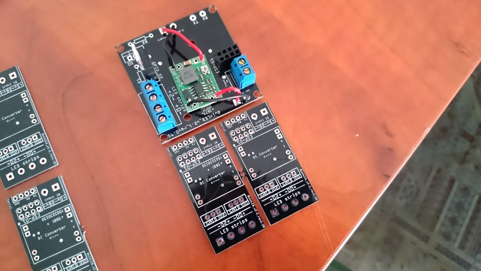 |
| The boards as they come in, same size as the previous board, just now 1 is 2! |
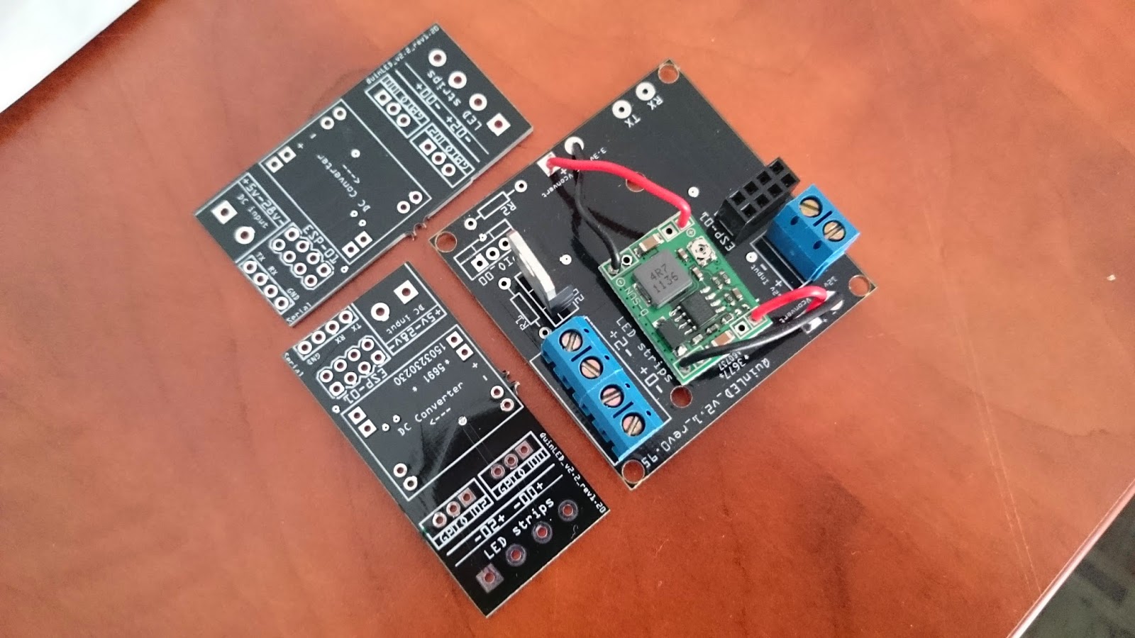 |
| Broken apart |
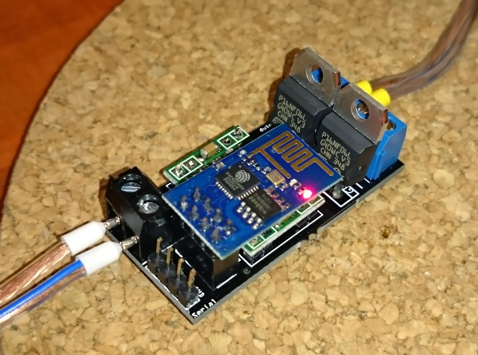 |
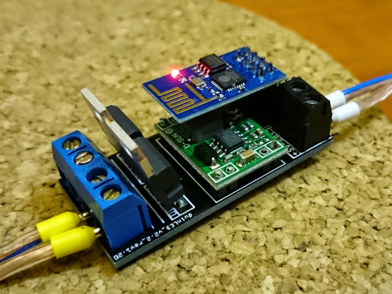
| Soldered together |
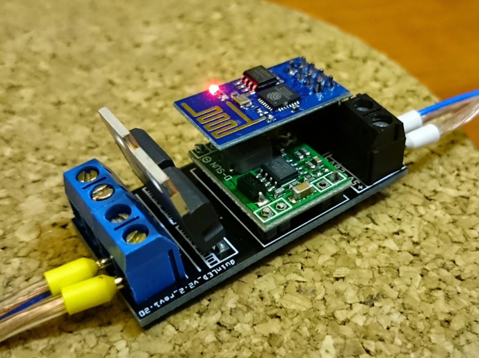 |
| Mosfets at an angle for easy soldering 😉 |
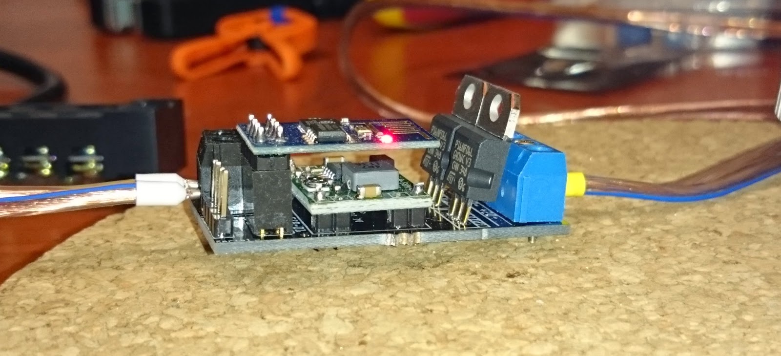 |
| Although close together there is more then plenty of clearance between the DC-DC converter and the ESP-01 |
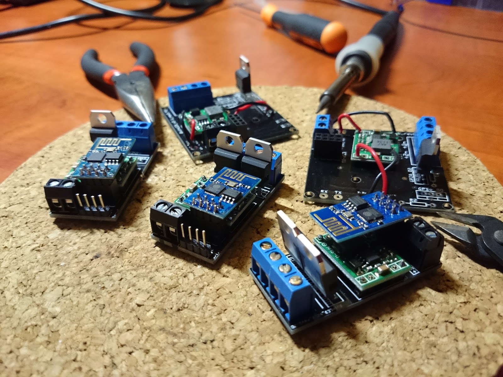 |
| Three boards soldered and ready for testing, old boards in the picture to compare |
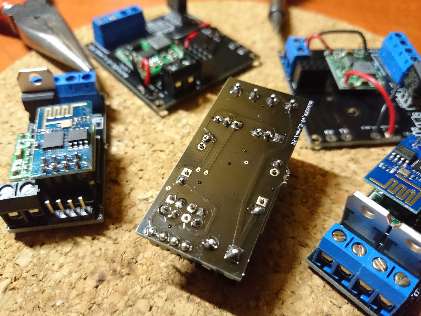 |
| Backside of the board where all the soldering is done |
“Instructions”
No real instructions are needed to solder the boards. All components used are clearly seen, a small list would be:
(For convenience I linked everything to the Aliexpress links where I purchased the components)
–update 2017-02-07
This series has since had a reboot and new component lists + (video) tutorials (also soldering) are available!
Check it out over here.
1×2 + 2×2 connectable wire terminals (RED) or (GREEN)
Some solder 😉
And that’s it.
Best instructions I can give you is to make sure you solder small to big components. Start with the header pins, then the DC-DC converter, then the 2×4 header for the ESP-01 and last the wire terminals and then the MOSFET(s).
When soldering the MOSFET(s) in place, make sure there is a little bit of room between them so that they are not touching, that could potentially be bad. 😉
!Make sure you set the DC-DC voltage converter between 3.3v and 3.6v before connecting the ESP-01! Per default these DC-DC converts come set to about 12v. It will kill your ESP-01 very quickly!
Ordering the boards
To finish, some more pictures of the board ‘in action’!
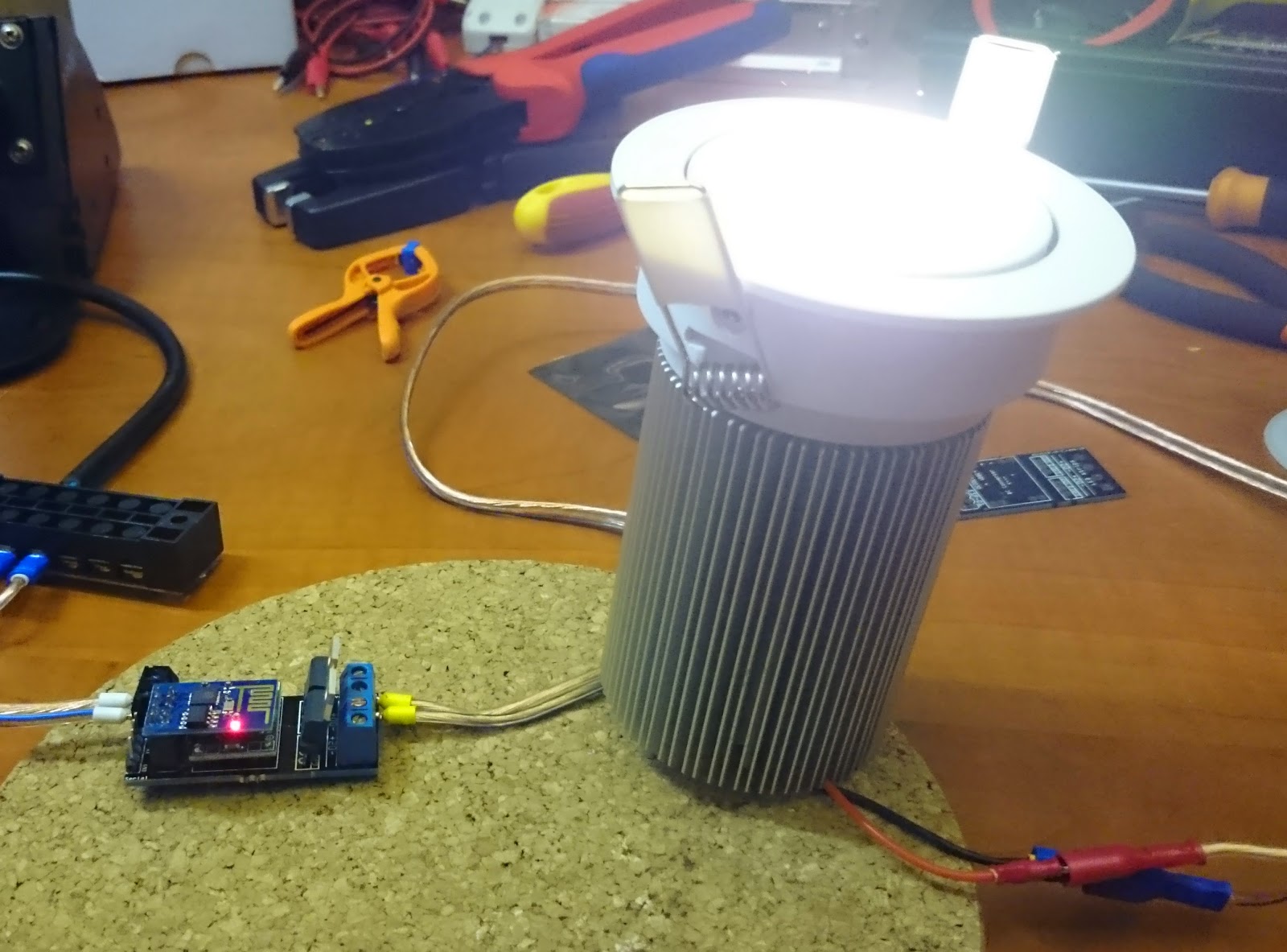 |
| 38.5v COB LED downlight |
 |
| 12v LED strip connected and running |


Can you provide a link for the mini dc converter?
Sure, coming right up. This post was in need of a good update anyway. Wrote it in a hurry to get it online!
Ordered the boards via the link provided, but while im waiting i quickly through it together on bread board. I have connected about 1m of led strip via 12v supply, but driving the MOSFET gate at 3v3 (the ESPs Max voltage) only switches the LEDs on very dim. Driving the gate at 12v through a resistor lights them at full brightness. i can't see how the LEDs could ever be at full brightness when driven from an ESP? What am i doing / getting wrong?
Are you running the ESP at 5volts! ? To get enough drive to the mosfets
I have at full brightness led strip to 9.2 volts? and also when you turn the dimer into a network of 220 volts is observed two bright LEDs flash then dim glow it's all up to management. with the office everything is fine. Thank you!. Sorry for bad English
Odd? This should work just fine. The gate switching voltage is 2v minimum, so 3.3v is more then enough to drive it. The voltage applied to the gate pin does nothing else then determine if the gate should be open or closed, it cannot regulate LED intensity.
This is done by pulsing the gate with a variable pulse size. Thus PWM. The default startup setting is a PWM value of about 15, the max is 1023. Are you sure you are changing the intensity after powering up the board?
Best to test is to startup the board and then remotely send the command to set the PWM value to the highest. That should give you full LED brightness output.
No, this should not be required. 2v is enough to open the gate pin 100% and thus trigger the drain to deliver what is connected to the source. PWM just does this very fast thus resulting in a dimmed LED.
I'm not sure I understand. But I believe you are trying to say that if you connected the dimmer it comes up at a lower dimm level and you need to send a command to set it to the brightness level desired. Then yes, you are correct!
@Chris Dobson You might want to double-check that your MOSFET part number has the "L" at the end. The "L" means "Logic Level" and the FET is designed to work with lower Vgs voltages. Take a look at the Id vs. Vgs curves for the 30N06L vs. the 30N06. The 30N06L is at Id of > 10A with around 3V of Vgs, whereas the 30N06 is at Id of < 1A with around 4V of Vgs. Just a hunch, but what you're describing seems like you have a non-logic-level MOSFET device.
I think you should put in a proper gate driving circuit for those FETs in order to keep them fully open and therefore as cool as possible even at higher loads. Simple 7-10V zener diode regulator and a NPN BJT for each FET's gate should be considered in the next revision.
Nevertheless, it is a very nice project, keep up the great work!
Ignore all my crap about the leds being too dim, it was me that was dim, ordered non logic level FET's
No problem, we make little mistakes sometimes. Good to hear it got sorted with the correct MOSFET's!
I am wanting to replace all the halogen down lights in my house with COB LED (MR16 base 12v) but it seems that all these LEDs contain a built in driver. Has anyone tried these with this dimmer ? Or would the driver circuit have to be removed from each lamp? And if several lamps with drivers removed, are connected to same dimmer, would the light output from each be uniform?
Amazing project! I was thinking to start something like that with my raspberry pi and my new esp8266 module, but I was totally blocked. Now everything is much more clear.
Thanks for these fantastic explanations.
How can i send commands to the dimmer using NodeRed ?
i have setup an inject node with string "echo Fadetimer1=9000,LED1_target=0" as the payload and connected it to a TCP Out node set as Connect to port 43333, Host 192.168.0.13 (the ip of my dimmer). Node Red has "connected" under the TCP node. when i press inject sometimes the dimmer does a hard restart, and needs to be re started. but mostly it does nothing Please help…….
Your last guess is correct. This would need to become the driver for each LED and they will all display the same light value. You do need to watch out though, this dimmer works with constant voltage, other drivers are often constant current and so you then need to figure out the voltage your LED needs.
Sorry, I have no experience with NodeRED. Did you try using the netcat command? That should work. If the module keeps crashing I suspect it's getting different input then you are supposed to send to it.
Thnx! That's why I try to put everything online! 😀
Your suggestion makes no sense to me whatsoever. :S
These are PWM driven MOSFETs. They have nothing to do with zener diode regulators and such.
Can this also be used as RGB led strip color control ?
In theory, yes. You need to add a third MOSFET and then change the code to accept it. Problem is that you don't have a third GPIO on the ESP-01. I would recommend going to a ESP-12 for that. More then enough GPIO pins!
Hi, I want to thank you for an interesting project.
I can not get any of your projects to work. I'm doing somthing wrong, but I did not manage to find it. (both dimmers and switches not work for me)
Domectic project with DS18B20 I manage to get to work for me.
I wish you did a zip file with the lua-file + nodemcu firmware you use.
It would be nice if you did a demo version to try mosfet function only. Dimm 0% – 100% – 0% repeating during 10sec.
I'm not sure what adding the code in the zip would accomplish. It would be exactly the same code as in the text parts.
When you copy the code into LUA Loader or ESPlorer (or any another serial tool) and save it to a file on the ESP module (for instance init.lua) and then reboot the module, what does it say?
My code should auto execute when you save it as init.lua and it should reset both channels to PWM on boot and set a value of PWM 15, thus dimly dimmed. Then you can try the netcat lines, Domoticz is a step beyond that, test manually first.
If it does not. Check the console output, it should state what is going wrong.
Hope this helps!
Hi,
Love this design, however I don´t have a need for 24 of these PCB´s. Are you willing (paid of course) to send 3 or so of these PCB´s to me? Please let me know if this is possible.
Many thanks for the design!
This comment has been removed by the author.
Hello,
Great Blog.
Any plan to release 220V mains line design in future?
Best Regards,
Saurabh
Hi,
Did you consider creating version with wired Wall Switch, I know you have wirelesses ones but is it 100 reliable, there is no option to tun off/on if there will be some issue with wifi.
Thanks
Great Blog. Have you idea how to replace MOSFET with TRIAC? dimming 230V?
Dimming 230V is totally different to dimming LEDs with PWM. The 230V is AC, and so must be done in phase with the AC waveform and (usually, I suppose) by delaying turn-on of the TRIAC.
Are you able to use these to power a solenoid(sprinkler valve)?
Hi
For those of us (or at least me) who are time poor, can you just sell the complete product along with instruction for how to add to wifi network and send commands?
Cheers
why not use AMS1117 3.3v SMD regulator? 12v -> 3.3v?! it works very well for me
Exactly what I have been looking for for years!
Just about to order my first batch 🙂
One question:
Is there an easy way to put the ESP8266 ESP-01 into "firmware flash mode" while it is on this new board?
I might want to build them into stuff and it would be cool if I didn't have to dismantle it to do firmware upgrades.
Would be cool if I could just have an "upgrade port" on my device where I could plug in the usb-to-serial adapter.
Thanks Quindor for sharing this very interesting project.
I was brought there from a forum and looking at the project there's something I don't have really clear. Does this device has the capability of connecting to a wall switch and manually activate/deactivate it?
I'm asking because where I come I was said that, but looking at it I can't see this provision.
Thanks again.
Hi, happy to see you here.
No, the dimmer module is currently not capable of accepting a switch input. It could be modified to do so but it's not really meant for that.
I am working on a different module which could do that as I showed in my other post where I tested the setup.
Thanks!
It should be also possible to include RGBW support with a module that has enough gpio pins. But I can't decide if wouldn't be better to just make a tiny switch module, perhaps battery powered and then place a big one on the main room box that controls all the lighting.
What do you think?
Mmmmmm other post?
I'm not sure I follow what you are trying to accomplish @Sergio Rius. Myself I'm running wire to all my LED lights and making a central control and power panel, but that will be another post. 😉
Hi, Quindor.
I'm thinking more of a main lighting solution. I mean, I'm not looking at this as ambient lighting, but replacing regular installation. You see, I've a three floor house with normal wall switches. I was thinking on changing the lighting current for the entire house to 12 volt, and adding a small ESP8266 to every switch to send commands to domoticz. Then every light point it's controller/dinner.
I don't know if a controller for all lights in the room or a simpler one on each.
@Sergio Rius interesting idea but take into account voltage drop over longer lengths of cable. For that reason I'm putting in a different circuit in my house which terminates at 4 closer points which prevents that problem. Also I'm running everything at 24v or 34v (depending on the type of light) to lower the issue with that problem.
Other then that, I'm also going to use it as main lighting system, but will still keep a backup 230v system in place just to be sure.
@Quindor I thought a bit about that, but didn't pay attention. It's a real shame, because a lot of energy is wasted on every power conversion. As a example, if we could generate 12v at solar panels, then store the energy on 12v batteries and directly power lighting from there without voltage drop would be fantastic. A lot could be saved on inverters and transformers.
I want to buy assembled board.Can you help me?
Hi Quindor. great post thanks. I was wondering if the same set up could support a ESP-03 module. if so would there be any major changes to the design?. thanks
Thanks for a great project tutorial!
I'm having the same problem as Chris Dobson.
I must push the gate voltage on the MOSFET to at least 4v for it to work.
I ordered the MOSFETs with the link you provided (STP16NF06L)
They do deliver 12v with 3,3v on the gate pin when nothing is connected to the output, but as soon as I connect something (tried with LED and solenoid), the voltage drops and I have to push the gate voltage to 4v for the voltage to get back up to 12v.
Ideas? Should maybe try with another MOSFET?
Amazing detailed walk through thanks so much for making this. I'm in the process of ordering all my parts right now. I was hoping to have the same set up as you here. But I wanted to simulate a sunrise using RGB LEDs. Would that just be a matter of changing to code?. I was going to use a ESP8862-03 instead as well, would much change compared to what you've done here using that wifi module?. Thanks again
Cheers MJ
Hi
It looks like you were able to configure the ESP-01 modules to just function with the GPIO-0 and GPIO-2 pins connected directly to the MOSFET?
When both the pins are floating have you had any issues getting the modules to boot? I keep having issues where the modules just hang and I want to smash.
I’ve read documentation where the pins need to be pulled high then used low as a sink but yours looks like it would function fine. The simplicity and logic all goes in line with what I assume should work.
I am running a different code on nodeMCU so I will need to experiment with that later.
Either way nicely documented, nice layouts, and your board layout is very neat. Encouraging for me to give it another try.
Thanks Quinder for posting this project , it is perfect and very useful .
I want to use this project to build my own warm / cool daylight led board for my canon camera , i chose the 5050SDM- 60leds/Meter – Watt:14.4W/Meter -LED Color:CCT=Cool White(6000-6500K)+Warm White(2700-3000K) .
1 – I believe that to be able to control both cool and warm white light , i will need to connect The Two Mosfet Drain outputs to the 2 pins of led strip “R & B” , please correct me if i am wrong .
2 – Does anyone knows what is the best led should be used to give a better result in daylight regarding the lumens , i see you use COB Led it looks very powerful brightness , can i use it and how many COB led of this can be connected to your board .
Thanks Again for this project .
AliExpress Link :http://www.aliexpress.com/item/5050SMD-LED-strip-color-temperature-adjustable-double-color-CW-WW-60LED-m-led-strip-free/32373777049.html?spm=2114.30010308.3.2.E6lG6N&ws_ab_test=searchweb201556_8,searchweb201602_5_10017_507,searchweb201603_11&btsid=677ab25e-f53f-42ea-abee-3f8d981c3f53
This is the right connection for the led strip to get control of Warm And Cool light .
How to connect ?
+12 / +24V——connect 12 / 24V ;
B —— connect “-” is Warm white ; To Mosfet 1
G —— connect “-” is Cool white To Mosfet 2
where to found eagle library for DC DC converter??
+1