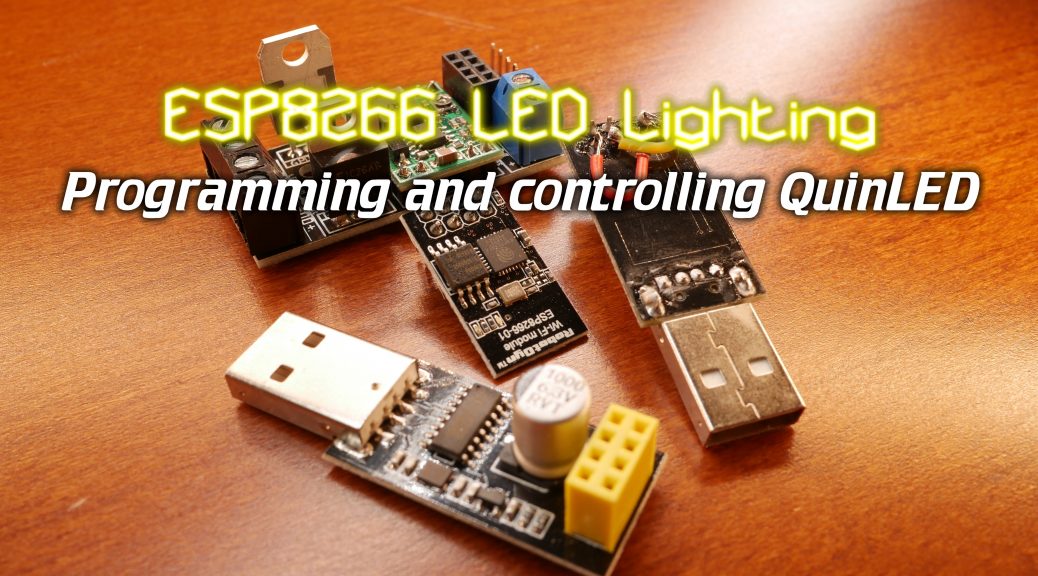
It’s been a while since the last article and video about the ESP8266 but finally the article and video on how how to program QuinLED and then control it from your PC is here!
This post is part of a series
The index for this series can be found here.
Video
As is now quite common I’ve made a detailed video about how to flash, program and then control the board. I will type it out in text form in this article too, but being able to see how it works always works best in my opinion!
New boards designs coming soon!
Currently, all DirtyPCB links are down because of a change to their website, coincidentally we also moved to the new house and officially don’t have any internet yet which is why the FTP site is ALSO down. So currently there is no way to order boards.
I have been working on a slightly optimized and updated board design though. I already have the first “print” in and just need to make a few corrections to it before it can be released into the world. So hold on just a bit longer, I should have them available soon!
Programs, firmware and code ZIP file
I have uploaded an updated ZIP file which contains all the programs, firmware and code you are going to need to use QuinLED.
Click the giant icon below to start the download.

Flashing QuinLED
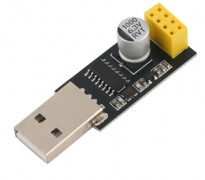
Since the last article I’ve acquired some convenient little USB adapters with a serial chip on-board which allow you to plug in and run an ESP-01 directly from your USB port. This saves a lot of time because you don’t have to fiddle with serial wires and such. Once you are done programming it, just plug it into a QuinLED board and you are done!
As can be seen in the video I have multiple of these little adapters of which I have modded one to always be in “flash mode”. That way I can very quickly flash an ESP-01, then plug it into a normal USB adapter, program it and them move it over to QuinLED.
I can certainly recommend getting a few of these! You can get them here. If you are uncomfortable soldering one yourself, you could also get this version which has a flash button on it!
*If you want more detailed instructions on how to use the flashing program, please look in the previous article (or watch the video)
Programming QuinLED
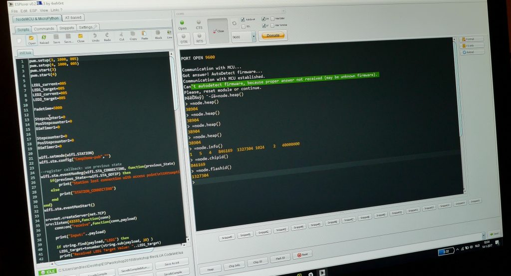
Once you’ve flashed the ESP-01 you want to use on the QuinLED board (either using serial wires or the USB adapter) open up ESPlorer. You will need to have Java installed for it to work.
Connecting to the ESP-01
ESPlorer should automatically detect the COM port your ESP is connect to, if not, select the right port and click op “open”.
That should open the serial port and make the connection with the ESP-01 module. Hit the “heap” button (lower part of the window) a few times and see if you get a response back. Often the first and second time will be a bit of garbage but after that it should work.
Loading the needed code
I’ve prepared a “init.lua” file which holds the whole program needed to have the ESP-01 make a network connection and perform the dimming functions.
In ESPlorer click the open file button and load the “init.lua” file included in the ZIP file.
There is lots of code in there! In a general overview it’s structured like this:
- Default boot settings for all values
- WiFi settings (we will need to edit these)
- Network socket server
- Command interpret and PWM dimmer routine
That’s a very high level over view, but this series isn’t about programming!
Program code
As written above, all the code is in the ZIP file you can download but if you’d rather copy and paste it, please also find it here:
pwm.setup(3, 1000, 005)
pwm.setup(4, 1000, 005)
pwm.start(3)
pwm.start(4)

LED1_current=005
LED1_target=005
LED2_current=005
LED2_target=005

Fadetime=5000

Stepcounter1=0
PosStepcounter1=0
DimTimer1=0

Stepcounter2=0
PosStepcounter2=0
DimTimer2=0

wifi.setmode(wifi.STATION)
wifi.sta.config("WIFISSID","PASSWORD")

--register callback: use previous state
wifi.sta.eventMonReg(wifi.STA_CONNECTING, function(previous_State)
    if(previous_State==wifi.STA_GOTIP) then
        print("Station lost connection with access point\n\tAttempting to reconnect...")
    else
        print("STATION_CONNECTING")
    end
end)
wifi.sta.eventMonStart()

srv=net.createServer(net.TCP)
srv:listen(43333,function(conn)
    conn:on("receive",function(conn,payload)

    print("Input:"..payload)

    if string.find(payload,"LED1") then
     LED1_target=tonumber(string.sub(payload, 28) )
     print("Received LED1 Target Value: "..LED1_target)

     Fadetime=tonumber(string.sub(payload,11,14) )
     print ("Received LED Fadetimer: " ..Fadetime)
     Stepcounter1=(LED1_target)-(LED1_current)

     if (Stepcounter1) < 0 then
      PosStepcounter1=(Stepcounter1)*-1
      else PosStepcounter1=(Stepcounter1)
     end

     if (PosStepcounter1) == 0 then
      PosStepcounter1=(PosStepcounter1)+1
      else PosStepcounter1=(PosStepcounter1)
     end

     DimTimer=(Fadetime)/(PosStepcounter1)

     if (DimTimer) == 0 then
      DimTimer=1
      else DimTimer=(DimTimer)
     end

     if (DimTimer) < 1 then
      DimTimer=1
      else DimTimer=(DimTimer)
     end

      print (Fadetime)
      print (Stepcounter1)
      print (PosStepcounter1)
      print (DimTimer)
      print (LED1_current)
      print (LED1_target)


    tmr.alarm(0, (DimTimer), 1, function()
     if LED1_current < LED1_target then
      LED1_current = (LED1_current + 1)
      pwm.setduty(3, LED1_current)
    elseif LED1_current > LED1_target then
      LED1_current = (LED1_current - 1)
      pwm.setduty(3, LED1_current)
    elseif LED1_current == LED1_target then tmr.stop(0)
     end end )
    end

    if string.find(payload,"LED2") then
        print("Received LED2 Target Value")
     LED2_target=tonumber(string.sub(payload, 28) )

     Fadetime=tonumber(string.sub(payload,11,14) )
     print ("Received LED Fadetimer: " ..Fadetime)

     Stepcounter2=(LED2_target)-(LED2_current)

     if (Stepcounter2) < 0 then
      PosStepcounter2=(Stepcounter2)*-1
      else PosStepcounter2=(Stepcounter2)
     end

     if (PosStepcounter2) == 0 then
      PosStepcounter2=(PosStepcounter2)+1
      else PosStepcounter2=(PosStepcounter2)
     end

     DimTimer=(Fadetime)/(PosStepcounter2)

     if (DimTimer) == 0 then
      DimTimer=1
      else DimTimer=(DimTimer)
     end

     if (DimTimer) < 1 then
      DimTimer=1
      else DimTimer=(DimTimer)
     end

      print (Fadetime)
      print (Stepcounter2)
      print (PosStepcounter2)
      print (DimTimer)
      print (LED2_current)
      print (LED2_target)


    tmr.alarm(1, (DimTimer), 1, function()
     if LED2_current < LED2_target then
      LED2_current = (LED2_current + 1)
      pwm.setduty(4, LED2_current)
    elseif LED2_current > LED2_target then
      LED2_current = (LED2_current - 1)
      pwm.setduty(4, LED2_current)
    elseif LED2_current == LED2_target then tmr.stop(1)
     end end )
    end
    end)
    end)

print ("Booted to QuinLED_ESP8266_V0.5.5")
Setting the correct WiFi network and password
In the code there is a line called:
wifi.sta.config("CampZone-pub","")
This is the line we need to change to match the settings for your home WiFi network.
To change it edit the line to contain your WiFi network details such as:
wifi.sta.config("blablaWiFi","pass123supersecret")
Saving and running the code on the ESP-01
To save the code to the ESP-01, hit the “Save to ESP” button below the code screen. This will start the transfer of the code line for line to the ESP-01 module.
After that’s done, hit “Save&Compile” and when that completes hit the “Reset” button.
Now your ESP-01 will be running the new code and should be connected to your WiFi network!
Checking if everything works and finding the IP address
The code uses DHCP to ask an IP from the WiFi network. But which IP did the ESP-01 get?
Using the command:
=wifi.sta.getip()
The module will report back which IP it got. Try and ping it to see if you can reach it!
Controlling QuinLED
Now that programming is done, the next step is controlling QuinLED to dim your LED lights!
Installing Netcat
To control QuinLED I make use of a program called Netcat. This is a little tool which uses TCP sockets to send text data to another network device. In the case of my QuinLED code this is using TCP 43333.
There is no official way to install Netcat (or NC for short). Mostly I just dump the entire contents of the ZIP file (included in the ZIP file above) into a directory that’s in the path (such as c:\windows\system32). After that you can run the command from anywhere but just calling “nc.exe”.
Sending a dim command to QuinLED
In the ZIP file I have also included the command line way to send dimming commands to QuinLED!
It looks like this:
echo Fadetimer=2500,LED1_target=888 | nc -w 2 IP.IP.IP.IP 43333
Fill in the correct IP number where it says IP.IP.IP.IP and try to see if the command works. If the ESP-01 receives the commands you should see some status messages scroll in the output window of ESPlorer.
If you did, that means everything is working and you are ready to connect the ESP-01 module to the QuinLED board. Or if it was already on there, you should have seen any connected LED strip dim to the desired value!
Ending remarks
And that should be it, you now have a fully WiFi network controllable LED dimmer!
Next in this series is how to use the same setup and connect everything to Domoticz given it all a nice front-end and automation capabilities!


Hi, Really love your project and have come to many of the same conclusions as you independently in terms of component choice and layout. Most of my troubles came from high mosfet threshold voltage which threw me a bit… We deviate a little in terms of software choice etc but the outcome is the same. Except I’m only at prototyping board level… Really learning a lot from your pcb posts and now checking out your youtube links so I can print some v2.5 rev 1.12 pcbs. I’m having troubles finding a good link for fritzing or dirtyPCB that is still live. Would love your help on that.
Hi Andries,
With the new USB adapter I could successful flash the ESP. And I can now dim the LEDstrip from the command prompt. I am looking forward for your next video with the connection to Domoticz.
regards,
Pino
Hii i’m getting tjhis error: when save&compile after Save To Esp.
NodeMCU 0.9.5 build 20150318 powered by Lua 5.1.4
lua: init.lua:25: attempt to call field ‘eventMonReg’ (a nil value)
> ÀŒÿ?°
The error was to not select the firmware *.bin on the flasher, now when i flash the correct firmware, of the package, on reset the esp8266 it starts to sending data with compilation error..
That was the error:
load 0x40100000, len 26404, room 16
tail 4
chksum 0x2b
load 0x3ffe8000, len 2204, room 4
tail 8
chksum 0x67
load 0x3ffe889c, len 136, room 0
tail 8
chksum 0x8b
csum 0x8b
rf_cal[0] !=0x05,is 0x00
ets Jan 8 2013,rst cause:2, boot mode:(3,7)
load 0x40100000, len 26404, room 16
tail 4
chksum 0x2b
load 0x3ffe8000, len 2204, room 4
ets Jan 8 2013,rst cause:2, boot mode:(1,6)
Hi XinuX, I’ve had a similar problem and raised it on his youtube page here https://www.youtube.com/watch?v=M7Lbr_u1iHs. I’ve not yet found a solution to this but have described the problem below. Please let me now if you find a solution. Heres what I sent to Andries…
Hi there. Love the videos and I managed to get my LED light dimming about 1 year ago using your code and setup. However, having sinced moved house and having rebuilt (change of IP address on the NodeMCU?) from scratch, I found errors were being reported by ESPlorer when sending test string to the node. i.e. “echo Fadetimer=2500,LED1_target=999 | nc -w 2 xxx.xxx.x.xx 43333”. The error reported was…
…
Booted to QuinLED_ESP8266_V0.5.5
> STATION_CONNECTING
Input:Fadetimer=2500
LED1_target=999
PANIC: unprotected error in call to Lua API (init2017.lua:45: attempt to concatenate global ‘LED1_target’ (a nil value))
…
where line 45 related to code
43 if string.find(payload,”LED1″) then
44 LED1_target=tonumber(string.sub(payload, 28) )
45 print(“Received LED1 Target Value: “..LED1_target)
I’ve tried fixing this in a number of ways including using (a) all of your workshop files, firmware and init.lua code (b) more recent builds of firmware (both master, dev and debug but always Integer builds – never float) and updating init.lua (in init2017.lua) reflecting updated versions of libary (especially wifi config). The problem seems to be in the “tonumber” part of line 44 which returns a null.
Just out of interest, does your implementation still work or are there a big changes in the required firmware build. Sorry, but I’m not a coder but reasonably good at following someone elses guide but have run out of ideas as to what to try next to get my PWM dimming working again. Let me know if can help and if you’d like more details of my setup.
Many thanks…
I’ve found the problem that I was experiencing. It was down to the loaction of 28 chars to find the number for LED1_target. 28 chars into the payload was actually pointing at the “=” sign so replaced 28 with 29 and it worked.
…but to get to this point, I used a new firmware build and had to update some of the wifi module calls to reflect more up to date usage in LUA 5.1. …and also replaced the hard definition of 29 chars by a call to string.find that returned the location of the “=” char, so just added 1 to it to get the number value to be converted by tonumber. e.g.
if string.find(payload,”LED1″) then
if string.find(payload,”LED1_target=”) then
startsub,endsub = string.find(payload,”LED1_target=”)
end
LED1_target=tonumber(string.sub(payload, endsub+1) )
print(“Received LED1 Target Value: ” ..LED1_target)
The only problem i now have is that I I still can’t get the LEDs to light-up or dim but think that’s an electrical issue.
Interesting to investigate this as it’s been many years since having touched any c-code.
hi , it is possible to configure a static ip??
Yes, sure, that’s a very easy change. Personally I leave it on DHCP and set a static lease on my DHCP server/router.
Nice project!
You considered making an zigbee version of the quinled as’well?
When designing it I looked at it but since microcontrollers with WiFi have become so cheap basically anything else would cost more. I also don’t see much added functionality by using Zigbee. Most people have WiFi coverage for the whole house now a days anyway. 🙂
does anyone have this working in Home Assistant? I’m using scripts to control the brightness and would love to use a slider.
Thanks
Hi,
adjusting it to the minimum, always ‘a lot of light …. and’ can adjust the range?
Thanks!!!!
Ps:
sorry for my english
If I after flashing the jumpers remove and plug the board into my computer (for programming) with a USBtoTTLmodule the blue light start flashing and don`t stop till I plug it out of my computer.
I already try a different esp01 but no succes. The flashing went flawless. What can be the problem?
Strange thing is going on. I’ve different ESP-01’s. A couple don`t want to connect (flash is working, but the don’t want to connect) and a couple works perfect. On the ones which don`t work is printed the name ‘ESP-01’ in the left above. On the ones which do working isn’t printed a name/type. What can be the problem here. Which types ESP-01 are suitable for your code and which one don’t?
Perhaps a late reaction, but are you sure you have the ESP01 instead of the ESP01S ?
https://www.esp8266.com/viewtopic.php?t=11657
the Programs, firmware and code ZIP files are not more available for download. Can i get a copy of it if anyone has? my Email ID is musheer.q@gmail.com